Download
1 / 144
1.46k likes | 1.65k Views
Introduction. The second industrial revolution radically changes the way we communicate virtually eliminating information lag.What problems does this create?. Recent Communications History. 1834 Samuel Morse invents the telegraph1876 Alexander Graham Bell makes the first long-distance phone call

E N D
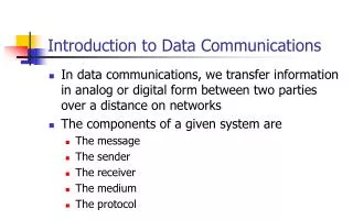
1. Chapter 1 Introduction to Data Communications
2. Introduction The second industrial revolution radically changes the way we communicate virtually eliminating information lag.
What problems does this create?
3. Recent Communications History 1834 Samuel Morse invents the telegraph
1876 Alexander Graham Bell makes the first long-distance phone call (10 miles)
1915 First transatlantic and transcontinental telephone service.
1948 Microwave links for telephone calls
1951 direct long distance dialing
4. Communications History Cont. 1962 Fax service is introduced
1965 widespread use of satellite long distance.
1968 Non Bell equipment allowed on phones system
1969 Picturephones
1969 DARPAnet
5. Communications History Cont. 1970 Limited long-distance competition allowed
1984 AT&T is broken up creating a regulatory boundary between local phone service and long distance
1984 Cellular phone service starts
1990�s Cellular phone service explodes
6. Communications History Cont. 1996 Telecommunications Competition and Deregulation Act replaced all federal and state telecommunications law
1997 68 countries sign agreement to allow foreign telecommunications competition
7. Information Systems History 1950�s Batch processing and punch cards
1970�s Real-time transaction-oriented database-driven systems emerge
1990�s Macys is bankrupt in part due to their �old� 1970�s era IS infrastructure
Read comparison between Macys and WalMart
8. Components of a Network Server � a device that stores data and often performs functions in addition to storage
Client � A terminal or microcomputer from which a user or other application performs a work function
Circuit � a wire, or set of wires and devices (modem, router, switch etc�) that carry information from the client to the server
9. Types of Networks LAN � Local Area Network
BN � Backbone Network
MAN � Metropolitan Network
WAN � Wide Area Network
Intranet � A network used within an organization
Extranet � Access for people from outside
10. Network Models Used to break networks into component functions (layers) which then allows each layer to be addressed independently.
The use of layers and different standards (and standards bodies) at these layers allows great flexibility in design, and competition between manufacturers.
11. OSI Model Produced in 1984
Consists of seven layers
12. Internet Model Similar to the OSI model
Compresses layers 5-7 into a single layer 5
The textbook author claims the internet model has won the �war�. Is this true?
13. Functions at Layer 4 (TCP) Error detection/correction
Linking higher layer software to the network layer
Name resolution
Breaking messages into pieces small enough to send over the network (MTU
14. Functions at Layer 3 (IP) Responsible for end-to-end routing of messages from sender to receiver
Responsible for attaining the next address for messages as they hop from router to router across the internet
15. Functions at Layer 2 Responsible for moving messages from the sender to the receiver within a LAN.
Controls the physical layer
Formats the messages
Provides error detection and correction
16. Functions at Layer 1 Get the signal (electrical signal, light pulse, smoke signal) from one LAN device to the next.
This layer includes hardware devices such as modems and hubs.
17. Two Types of Standards Formal
Developed by an official industry or government agency
These are often slow in developing and follow an already existing de facto standard
De facto
Emerge in the marketplace and are supported by multiple vendors but have to official standing
18. Standards Making Bodies IEEE
The Institute of Electrical and Electronic Engineers
Professional organization based in the United States
Primarily responsible for existing LAN standards
19. Standards Making Bodies ITU-T
Responsible for creating technical standards for the united nations international telecommunications union (ITU)
Open to public or private operators of communications networks from more then 200 countries
Based in Geneva Switzerland
20. Standards Making Bodies IETF
Internet Engineering Task Force
Open to everyone
Manages consensus-building process through the use of RFC�s
Oversees creation of Internet protocols and standards
21. Future Trends Pervasive networking
Integration of voice, video and data
New information services
22. Chapter 2 Application Layer
23. Application Architectures Host-Based Architectures
Commonly a mainframe with terminals
Client-Based Architectures
Distribute PC based architecture with the computing power at the desktop
Client-Server Architecture
Applications software divided between desktop PC�s and central servers (fat vs. thin clients)
24. N-tier Architectures Two-tier
A client talks to a server (connecting to a web server)
Three-tier
A client talks to a web server which in turns queries a database server to obtain the requested data
N-tier
Same concept applied N times
25. Advantages of Client-Server Scalability
N-tiered architecture gives a high degree of scalability
Cost of infrastructure
A set of smaller micro or mini computers and the associated software is often far less expensive then a mainframe approach
26. World Wide Web Create in 1989 at the CERN lab in Geneva Switzerland by Tim Berners-Lee
A graphical interface was developed in 1993 by a team of students led by Marc Andreessen at the NCSA lab at the University of Illinois
Adoption of the technology was immediate and rapid
27. Electronic Mail One of the earliest applications on the Internet (Early �killer� app)
Cost and speed are among it�s strengths when compared with �snail mail�
Important protocols and extensions to understand
SMTP (Simple Mail Transfer Protocol)
IMAP (Internet Message Access Protocol)
MIME (Multipurpose Internet Mail Extension)
28. Other Important Applications Listserv
A mailing list of users who have joined to discuss a topic or receive specific information updates
Usenet
A repository of articles on many different subjects
29. Other Important Applications FTP � File Transfer Protocol
Provides the ability to transfer data to and from systems (primarily used in conjunction with UNIX servers)
Telnet
Provides the ability to login to a server from anywhere within a connected network
The name is derived from making a TELephone connection via the NETwork.
30. Chapter 3 Physical Layer
31. Components in Physical Layer Media
Wires, fiber-optic strands
Wireless
Special-purpose devices
Modems
Repeaters/hubs
32. Circuits Physical Circuit
Twisted pair cable, fiber, wireless link
Exclusively committed to your data
Logical Circuit
One of several, perhaps many circuits on a single physical circuit
Channel 12 on TV is a logical circuit, it rides on a coaxial cable or wireless (a physical circuit) along with many other logical circuits
33. Types of Data Digital
Two possible values for any data bit (1 or 0)
In a fiber circuit a light being on could represent a �1� while off represents a �0�
In a copper circuit 5 volts could represent �1� while 0 volts represents �0�
Analog
Signals are shaped like sound waves and are constantly changing
34. Modem/Codec MOdulate/DEModulate
Translates digital data into a form that can be transmitted across an analog circuit such as a standard telephone line
COder/DECoder
Translates analog information into a form that can be transmitted across a digital circuit
35. Circuit Configuration Point-to-Point
A circuit with a device at each end
Home modem
Multipoint
A single device at one end with many devices at the other end with either time-slicing or circuit switching
36. Data Flow Simplex
One way transmission (i.e. cable TV)
Half-duplex
Communication in both directions, only one way at a time (i.e. walkie-talkie)
Full-duplex
Communication in both ways, at the same time (i.e. telephone)
37. Communication Media Guided media
Twisted-pair, coaxial, fiber-optic
Wireless media
Radio, infrared, satellite
38. Fiber Optic Multi mode
Attenuation (weakening of the signal)
Dispersion (spreading of the signal)
Single mode
Must use the precision of lasers as opposed to LED�s
39. Coding Character
A symbol with a constant understood meaning
Byte
A group of (typically) eight bits that is treated as a character
ASCII (American Standard Code for Information Interchange)
7 or 8 bit code (typically 8)
40. Transmission Modes Parallel
All bits are sent simultaneously, in a 32-bit system then there must be paths to send all 32 bits at the same time
Serial
Each bit is sent one at a time,
41. Digital Transmission Transmission of 1�s and 0�s
With electricity this can be voltages with perhaps 0 volts representing a zero and 5 volts representing a 1 (unipolar)
With light this can be using the state of the light with perhaps off representing a 0 and on representing a 1
42. Manchester Encoding Used in Ethernet
Unipolar coding scheme with a twist
Voltage moving from a lower level to a higher level represents a �1�
Voltage moving from high to low is a �0�
43. Analog Transmission Telephone systems were originally designed to carry analog transmissions, electrical representations of the human voice
Three key characteristics
Amplitude
Frequency
Phase
44. Modulation A carrier wave (ugly noise heard when modems are negotiating) is sent between modems, the shape of the wave is altered to represent 1�s and 0�s
These �shape changes� are referred to as modulation
45. Modulation Techniques Amplitude
Modifying the height of the wave
Frequency
Modifying the frequency (the number of waves per second) of the wave
Phase
Modifying the point in phase at which the wave starts
46. Amplitude Modulation
47. Frequency Modulation
48. Phase Modulation
49. Two-bit Amplitude Modulation
50. Modulation Techniques The various modulation techniques discussed can be combined as well
QAM (Quadrature Amplitude Modulation)
Combines eight phases (three bits) and two amplitudes (one bit) for a total of four bits
TCM (Trellis Code Modulation)
Similar to QAM but can transmit up to ten bits per symbol
51. Bits Baud and Symbol Bits (specifically bits per second) are generally the important measurement in data communications as symbols are composed of bits
There is a common misconception that these terms are interchangeable, baud refers to the number of symbols per second as opposed to the number of bits per second
52. Voice Circuit Capacity Home analog phone lines have a bandwidth range from 0 to 4000 Hz
The human ear can detect sounds up to ~14,000 Hz so very high pitch sounds can�t be transmitted over an analog phone line
Digital circuits used to tie analog phone lines together have a bandwidth of 64,000 bits per second (bps)
53. Modem Technologies V.34+
Transmits up to 33,600 bps
V.44 (Compression)
Builds a dictionary of character combinations being sent over the circuit
When a combination is repeated the dictionary reference is sent as opposed to the characters
Average throughput is ~ 6:1
54. Codec Converts Analog data into a digital form for transmission over a digital system and back
The analog signal is translated into a binary number
This digital signal is an approximation of the original with the quality depending on the resolution by either increasing the amplitude levels or increasing the sampling rate
55. Telephone Transmission The �local loop� is the circuit from the phone company CO (the building between 3rd and 4th streets and Chestnut and Hazel streets) uses analog transmission
Once the signal reaches the phone company office it is converted to digital form and is then sent to it�s destination CO
Even local calls are converted to digital
56. Pulse Code Modulation PCM is used in phone company CODEC�s in North America
PCM samples the data 8,000 times (twice the highest frequency within the phone system
Eight bits are generated for each sample, thus the phone system uses the 8 bits * 8,000 samples for a data rate of 64,000 bps
57. ADPCM Adaptive Differential Pulse Code Modulation
Similar to PCM except it only sends the difference between the former and the new signal
Data rates as low as 8Kbps can be obtained, 32Kbps is the lowest providing sufficient quality so that the user doesn�t notice
The use of ADPCM is the reason that some users can�t get a modem connection above 26,200 bps
58. Analog/Digital Modems Uses PCM backward
Sends 8,000 samples per second
Uses 7 bits (one is lost for control purposes
7 bits * 8,000 samples = 56,000 bits
V.92 modems do this in each direction and due to technical constraints are limited to ~52,000 bps downstream and ~42,000 bps upstream
59. Multiplexing Using one high-speed circuit to carry the traffic of multiple lower-speed circuits
FDM
TDM
WDM (form of FDM)
DWM (combination of FDM and TDM)
Has reached 1.25 terabits already and is expected to reach 1 petabit within a few years
60. Frequency Division Multiplexing
61. Time Division Multiplexing
62. Inverse Multiplexing Using a series of lower-speed circuits to connect two high-speed circuits together
Technology has been proprietary until just recently
The BONDING (Bandwidth ON Demand Interoperability Networking Group) standard is allowing vendors to interoperate today but this is still in its infancy
63. Inverse Multiplexing
64. Digital Subscriber Line Much of the available bandwidth in the local loop has gone unused for many years
DSL uses this bandwidth by applying FDM to create three circuits comprised of the original phone line, a upstream data circuit and a downstream data circuit
TDM and PM are also used to obtain various data rates and features
65. Chapter 4 Data Link Layer
66. Media Access Control A mechanism used to control when computers transmit
Important when using half-duplex circuits or multipoint configurations
Two fundamental approaches
Controlled Access
Contention
67. Controlled Access X-ON/X-OFF
Polling
Roll Call Polling: one device in the circuit is a �master� and checks with each other device on its wire to see if they have something to say
Hub Polling (token passing): one computer starts the poll and passes it to the next, when a computer with something to say receives the �token� then it can send its data
68. Contention The opposite of controlled access, each device listens to see if someone else is talking, if not then it sends carrier and starts to talk
CSMA/CD (Carrier Sense Multiple Access with Collision Detection) is used in Ethernet networks
69. Network Errors Two types of network errors
Data loss
Data corruption
Three approaches to dealing with errors
Prevention
Detection
Correction
70. Sources of Errors Line noise, distortion
Line outages
Impulse noise
Cross-talk
Attenuation
Intermodulation noise
Jitter
71. Error Prevention Shielded cabling
Cable location
Cable selection (fiber vs. twisted pair)
Cable installation and maintenance
72. Error Detection Parity
Longitudinal redundancy checking
Polynomial checking
Checksum
Cyclic Redundancy Check
16-bit CRC used in TCP
32-bit CRC used in Ethernet
73. Error Correction via Retrans. Stop-and-wait ARQ
Continuous ARQ
74. Forward Error Correction Sufficient redundant data is included within the transmission to correct errors without retransmission
Used heavily in satellite transmission
75. Ethernet Protocols Ethernet (IEEE 802.3)
Byte-count protocol
Destination, length, LLC, SNAP, CRC-32
Point-to-Point Protocol (PPP)
Address
Protocol
Message length = 1,500 bytes
76. Bridging/Switching MAC-layer address table for each interface
Addresses behind a port are stored in memory
Ethernet frames are checked at each interface to determine if they should be forwarded
77. Transmission Efficiency Transmission efficiency = total information bits/total bits
Throughput = transmission efficiency adjusted for errors and retransmissions
TRIB
78. Chapter 5 Network and Transport Layers
79. TCP/IP TCP
Layer 4
Provides error detection (CRC-16)
Breaks data into appropriate size blocks (MTU)
IP
Provides routing and addressing
IPv4 (32-bit address)
IPv6 (128-bit address)
80. TCP Ports A computer can have multiple applications running, i.e. a machine can be running both a web server and an email server
Commonly used ports
SMTP � port 26
WWW � port 80
FTP � port 21
Telnet � port 23
82. Packetizing Taking an outgoing message with a length too great to fit within the data-link maximum frame length (MTU) and breaking the message into appropriate lengths
Function is performed by the transport layer
With IPv4 the packet size is set for the local LAN and is adjusted if the message is sent across a link that requires a smaller MTU
83. Connection-oriented Routing A specific route �virtual route� is determined when the session is created
A SYN packet is sent to create the virtual circuit
A FIN packet is sent to tear the circuit down
84. Connectionless Routing Uses UDP instead of TCP
Packets can travel different routes
Commonly used with applications such as DNS and DHCP which are not likely to send a packet that will have to be broken into pieces
85. Quality of Service A special type of connection-oriented routing
Classes of service are established and each application is assigned one of the classes
Applications such as VoIP and video-conferencing may be in a higher priority class then SMTP or WWW
86. Internet Addresses Assigned by ICANN (Internet Corporation for Assigned Numbers and Names)
Blocks of network addresses are assigned to organizations
Often a large block of addresses are assigned to an organization
These large blocks of addresses are broken into smaller blocks referred to as �subnets�
87. Subnets There are many possible combinations when dividing a network address block into subnets
It is also possible to merge two adjacent networks together into a single �supernet�
Whether dividing a network into subnets or combining two or more networks into a supernet the subnet mask is the key
88. Subnet Mask A subnet mask is a string of 1�s and 0�s
A subnet mask of 255.255.255.0 indicates the first three bytes of the IP address are part of the network
Another way of looking at this subnet mask would be 11111111.11111111.11111111.00000000
A 1 indicates the corresponding bit in the IP address is part of the network designation
89. Dynamic Addressing DHCP (Dynamic Host Configuration Protocol)
When the computer is started it sends a message requesting that a DHCP server provide an IP address and other configuration allowing the computer to communicate via IP
90. Layer 2 Address Resolution ARP (Address Resolution Protocol)
Broadcast Message (all 1�s)
Whoever has IP address xxx.xxx.xxx.xxx send me your Ethernet address
91. Domain Name Service An Internet phone book
When typing in www.csuchico.edu DNS will translate this application-layer address to the network-layer address of 132.241.82.24
92. Routing Packets are routed between networks based on a set of routing tables
The routing tables can be manually programmed (static routing) or created by a routing protocol (dynamic routing)
Routing Protocols
Distance Vector (RIP)
Link State (OSPF)
93. Routing Protocols Interior routing protocols
RIP, OSPF, EIGRP
Exterior routing protocols
OSPF, BGP
Autonomous System
94. Multicasting Three types of messages
Unicast
Broadcast
Multicast
IGMP (Internet Group Management Protocol)
Each participating computer uses a common data-link layer address
95. TCP/IP Example Work through the entire TCP/IP example at the end of chapter 5
Known addresses, same subnet
Known addresses, different subnet
Unknown addresses
TCP connections
96. Chapter 6 Local Area Networks
97. Why Use a LAN? Information Sharing
Email
File access
Video conferencing
Resource Sharing
Printers
Applications servers
98. Dedicated Server vs. Peer-to-Peer Dedicated Server
One or more server computers permanently assigned to being a network server
File servers
Print servers
Peer-to-Peer
No dedicated server
99. LAN Components NIC (Network Interface Card)
Network cables
Twisted pair
UTP/STP
See Category Ratings in Technology Focus
Coaxial cables
BALUNs
Fiber-optic cables
Single-mode vs. multi-mode
100. LAN Components Cont. Network hubs
Network bridges/switches
Network routers
Network Operating System
Server/client software
Network profile
Storage Area Networks (SAN)
Network Attached Storage (NAS)
101. Ethernet (IEEE 802.3) Topology
Logical vs. physical
The logical topology of a traditional Ethernet network is a bus
The physical topology is often a star
102. Media Access Control With a bus topology there must be a mechanism to either prevent, or detect and deal with, collisions on the media
CSMA/CD
Full-duplex Ethernet
103. Types of Ethernet 10Base-5
10Base-2
10Base-T
100Base-T
10/100 Ethernet
1000Base-T
104. Switched Ethernet The switch replaces the hub in the network
The hub repeats every bit of data out every port
The switch sends the data out the port which is connected to the message recipient
The switch uses a forwarding table that contains the Ethernet addresses of the computers connected to each port
105. Wireless Ethernet IEEE 802.11
The WEP standard has been completely cracked
Uses CSMA/CA for media control
Subject to the �hidden node� problem
Has VCSM (Virtual Carrier Sense Method) as an option to work around the hidden node problem
106. Types of Wireless Ethernet IEEE 802.11b
DSSS � Allows speeds from 1 � 11 Mbps depending on distance and interference
FHSS � Allows speeds from 1 � 2 Mbps
IEEE 802.11a
The standard is still incomplete
Data rate is likely to be 54 Mbps on first iteration
Actual throughput will likely be ~20Mbps
107. Other Wireless Technologies Infrared wireless
Requires line of site or white ceilings and walls with diffused infrared
Bluetooth
Slated to become standardized as IEEE 803.15
Short range networks referred to as piconets with no more then 8 devices
Uses controlled access media access control
Less then 1Mbps throughput
108. Reducing Network Demand Placing heavily-used applications or data modules on each client computer
Network segmentation � note this is really increasing supply rather then reducing demand
109. Chapter 7 Backbone Networks
110. Backbone Network Components Bridges
Operating at the data-link layer (MAC address)
Routers
Operating at the network layer (IP address)
Gateways
Operating at the transport layer (note that this disagrees with the authors table 7-1)
111. Backbone Network Components Collapsed backbone
Chassis-based
Rack-based
VLAN�s
Port-based
MAC-based
IP-based
Application-based
112. ATM Four key differences between Ethernet and ATM in the backbone
53-byte fixed-length cells
No error correction
Virtual Channel addressing as opposed to fixed addresses with the path and circuit numbers
Built in Class-of-Service (CoS) and Quality-of-Service (QoS)
113. ATM Classes of Service
CBR
VBR-RT
VBR-NRT
ABR
UBR
LANE vs. MPOA
SVC vs. PVC
114. Chapter 8 MAN�s and WAN�s
115. MAN�s Generally constrained to a city or small region between 3 and 30 miles
Generally deployed via either wireless technology or services leased from a carrier
Moderate levels of regulation
116. WAN�s Connecting over potentially great distances
Generally deployed via circuits leased from Common Carriers
Very heavily regulated within North America and usually even worse oversees
117. Circuit Switched Networks Usually depicted by a cloud with your organizations data traveling with many others across the same physical circuits
POTS
ISDN
BRI
PRI
Broadband
118. Dedicated Circuit Networks Dedicated circuits or dedicated bandwidth within carrier circuits
Ring Architecture
Star Architecture
Mesh Architecture
119. T Carrier Services Based on the 64Kbps channel required for a digitized voice connection
T1 � 24 channels * 64Kbps = 1.536 Mbps
Control information is included bringing the total circuit bandwidth for a stand-alone T1 to 1.544 Mbps
T3 � 28 T1�s � 28 * 1.544Mbps = 43.008Mbps
With control information = 44,736Mbps
120. SONET SONET is a North American standard but the ITU recently adopted the SDH standard set which is nearly identical
OC-1 = 51.84Mbps
OC-3 = 3*OC-1 = 155.52 Mbps
OC-12 = 12*OC-1 = 622.08 Mbps
121. Packet Switched Networks X.25 � older standard now seldom used in North America
ATM
Frame Relay
Ethernet/IP Networks
122. Virtual Private Networks Intranet
Used to connect your organizations office via the Internet
Extranet
In addition to your organizations office you may also include other organizations with which you do business
Access
Remote access for employees
123. Chapter 9 The Internet
124. Internet Structure Internet architecture
NAP�s, MAE�s, and ISP�s
POP�s
Peering
Autonomous systems
125. Internet Access Technologies DSL
Digital Subscriber Line
Uses the local-loop
A modem is placed in the home converting the data from the DSL format to Ethernet
ADSL
G.Lite
VDSL
126. Internet Access Technologies Cable Modems
DOCSIS
Shared media means users compete with each other for bandwidth and unscrupulous neighbors could intercept your data
Throughput suffers due to hardware compatibility issues that stem from cable TV infrastructure differences
127. Wireless Fixed wireless
Wireless DSL
Satellite
Mobile Wireless
WAP
WAE
128. Internet Governance ISOC (Internet SOCiety)
www.isoc.org
IETF (Internet Engineering Task Force)
IESG (Internet Engineering Steering Group)
Each IETF working group is chaired by a member of the IESG
IAB
IRTF
129. Internet Domain Name Reg. Internet name and address registration was handled by John Postel until his death in 1998
In 1998 ICANN (Internet Corporation for Assigned Names and Numbers) was formed
In 1999 ICANN established the SRS and has now authorized more then 80 companies to issue Internet names and numbers
130. Internet 2 Next Generation Internet
vBNS
Abilene
CA*net 3
131. Chapter 10 Network Security
132. Why Networks Need Security The average cost to companies for a single security breach is slightly less then $1M
This is a minor cost when compared to the loss of customer confidence
The text indicates that 24 hours of downtime would cost Bank of America $50M
133. Types of Security Threats Disruptions
Minor cable breaks to earthquakes
Unauthorized Access
More often the work of an employee then an outside hacker
134. Network Controls Controls are processes or steps to reduce or eliminate threats
Three types of controls
Controls that prevent threats
Controls that detect threats
Controls that correct threats
135. LAN Security Although sometimes overlooked a good first step is to ensure that the LAN hardware is physically secure
Firewalls
Packet-level
Application-level
NAT (Network Address Translation)
136. LAN Security Encryption
Symmetric
DES
Triple DES
AES
Asymmetric (PKI)
PGP (Pretty Good Privacy)
SSL (Secure Sockets Layer)
IPSec (IP Security)
137. Detecting Unauthorized Access IDS (Intrusion Detection Systems)
Network-based
Host-based
Application-based
Two IDS Techniques
Misuse detection
Anomaly detection
138. Chapter 11 Network Design
139. Network Design Process Traditional design process
Building Block Design Process
Needs analysis
Technology design
Cost assessment
Why network projects fail
Management focus 11-2
140. Request For Proposal Background information
Network requirements
Service requirements
Bidding process
Information required from vendor
141. Chapter 12 Network Management
142. Network Management Tasks performed by the network manager
Five key management tasks
Key network management skills
Configuration management
143. Performance & Failure Statistics Availability
MTBF
MTTRepair
Policy-Based Management
Service-Level Agreements
144. Cost Management Sources of cost
TCO (Total Cost of Ownership)
$8,000 - $12,000 per device per year?
$1,500 - $3,500 per device per year? (NCO)
Five steps to reduce network costs
145. Network Management Tools Three types of network management software
Device management
System management
Application management
SNMP
MIB
RMON