Download
1 / 23
360 likes | 793 Views
CONSTRUCTION BLUEPRINT READING. RISER DRAWINGS. CONSTRUCTION BLUEPRINT READING. Riser diagrams or single line diagrams are used to show the arrangement of equipment and wiring. Riser diagrams show the connecting lines used for feeders and cable distribution per each floor serviced.

E N D
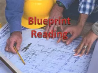
CONSTRUCTION BLUEPRINT READING RISER DRAWINGS
CONSTRUCTION BLUEPRINT READING • Riser diagrams or single line diagrams are used to show the arrangement of equipment and wiring. • Riser diagrams show the connecting lines used for feeders and cable distribution per each floor serviced. • They will provide conduit sizes, shown on the electrical riser diagram, and backbone counts to each floor.
CONSTRUCTION BLUEPRINT READING • For low voltage systems the grounding riser will be shown, in some cases this may be a detail drawing. • Notice that the TMGB is connected to the service equipment in the electrical entrance facility.
CONSTRUCTION BLUEPRINT READING • The electrical entrance facility has an earth ground connected to the electrical service equipment, this is the starting point of the grounding electrode system, and a bonding conductor is connected to the TMGB.
CONSTRUCTION BLUEPRINT READING • From the TMGB a TBB is run to each TGB in each TR. • What size TBB is required for this electrode grounding system? (it is assumed you should know this, its not stipulated on this riser diagram). 6 AWG
CONSTRUCTION BLUEPRINT READING • Riser diagrams may include a general notes section and a legend as seen in the grounding riser diagram.
CONSTRUCTION BLUEPRINT READING • In this riser diagram the general notes tell us that we need to install a 100 pair to each TR from the entrance facility and a 12 strand MM fiber from the data center to each TR.
CONSTRUCTION BLUEPRINT READING • Looking at this diagram you now know you will have two separate pulls from two different locations. • You will need to look at detail drawings to determine where in each of these rooms the cables will terminate.
CONSTRUCTION BLUEPRINT READING • Here is a detail drawing of a TR;
CONSTRUCTION BLUEPRINT READING • If this was the detail drawing for the riser system shown then the 100 pair cable will emerge from one of the 4” conduits and terminate on a back board. BASED ON THE INFORMATION GIVEN IN THE DRAWING THE 100 PAIR CABLES WILL TERMINATE ONTO WHAT TYPE OF BLOCKS? BIX BLOCKS
CONSTRUCTION BLUEPRINT READING • The riser diagram is representative of the scope of work and needs to be compared with the floor plans for the location of the spaces.
CONSTRUCTION BLUEPRINT READING • How many and what size 110 blocks are required for the riser installation portion of this project? 1, 300 pair block for the entrance facility and 3, 100 pair blocks, 1 for each of the TRs.
CONSTRUCTION BLUEPRINT READING • When working on high rise projects the riser diagrams will need to be split up into sections. Here is a 19 story building not including the sub-levels. South and East elevations are shown in this drawing.
CONSTRUCTION BLUEPRINT READING • Here is the legend to explain the devices for the riser system.
CONSTRUCTION BLUEPRINT READING • The fire alarm riser diagram would also include a general notes section for further details on the riser installation. • It is typical for the general notes to refer you to other drawings for specifics, as an example the actual device counts would be on a separate floor plan. • The riser diagram shows only the east and west wing set up but not the number of devices required for full protection of the wing.
CONSTRUCTION BLUEPRINT READING • Notice that the DS and TS are attached to the AHU,the AHU is the air handling unit, that has a duct sensor DS in it, the DS is wired to a test switch TS. • These test switches can be seen in the hallways of the school and are labeled with the AHU number that they’re associated with.
CONSTRUCTION BLUEPRINT READING • There will also be detail drawings for wiring the different circuits in a fire alarm system;
CONSTRUCTION BLUEPRINT READING HERE IS A VOICE AND DATA RISER AND DISTRIBUTION DETAIL DRAWING, THIS DETAIL SHOWS HOW THE VOICE LOCATIONS ARE WIRED TO THE PBX, WHAT IS NOT SHOWN IS HOW THE DATA HUBS ARE CONNECTED.
CONSTRUCTION BLUEPRINT READING • In the previous diagram the abbreviation LEC is used, what does LEC stand for? LOCAL EXCHANGE CARRIER (PHONE COMPANY)
CONSTRUCTION BLUEPRINT READING • Here is an electrical riser diagram
CONSTRUCTION BLUEPRINT READING • This is a small section cut from the riser diagram, as you can see some of these drawings can get pretty complicated.
CONSTRUCTION BLUEPRINT READING • The circle show a call out to a detail drawing, the rectangle refers you to specific general notes and the square shows a circuit to the fire alarm control panel with the type and amperage of the fuses for the circuit.