Download
1 / 7
90 likes | 183 Views
Best Practices for Sheet Metal Design. We all know there are multiple ways to construct models in SolidWorks. No single method is better or worse than another, but some methods will allow for:. 1. Easier modifications to models. 2. More robust or stable models. 3. Models that are “smart”.

E N D
Best PracticesforSheet Metal Design We all know there are multiple ways to construct models in SolidWorks. No single method is better or worse than another, but some methods will allow for: 1. Easier modifications to models. 2. More robust or stable models. 3. Models that are “smart”. 4. Models that are more useful for everyone. Developing Best Practices is our way to identify which methods work best for the types of designs we create everyday.
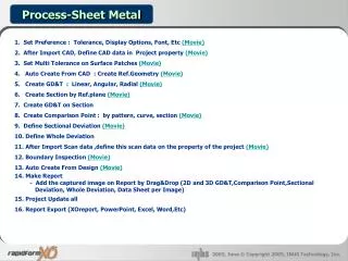
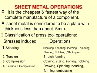
Sheet Metal Design Tips Design Tips: 1. Consider the final orientation of your new part, as it will be used in the final assembly, and select the corresponding Plane to start your sketch. 2. Always sketch your parts with sharp corners, don’t try to sketch the bend radius of your part. Let SolidWorks determine the radius of the Bends based on data in the Process-bends feature. 3. Always constrain a sketch to the Origin of your part. 4. Try to fully define your base sketch. A fully defined sketch turns all your sketch segments black by default.
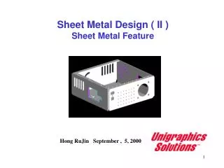
Extrude your shape Extrude your shape the required distance. Depending on the orientation and design intent of your part, you may extrude in One Direction or Mid-Plane. One Direction is good if the end of the part is used as a datum in your assembly. Mid-plane is good if the part has to stay symmetric.
Adding Features When adding features, fully constrain your sketches once again. The design intent of your feature sketches will determine how they should be driven by your dimensions. If you have similar items in your feature sketches, try to add Relations that will help maintain your design intent. In this example, the 2 circular sketches have an Equal relation applied to ensure they stay the same size.
Applying Bends To insert sheet metal Bends, select a flat face of your model. Ensure your Bend Parameters are set to company standards to generate usable flat patterns. Our Bend Parameters are: K-factor= 0.434, Auto Relief= Obround at 0.250
Adding Features after Bends If you need to add a feature, make sure you rollback the Feature Manager bar to a point before your Sheet-Metal feature. This will ensure the feature is included in the flat pattern of your model. For some features such as countersinks and counterbores, users may want to create these after Process-Bends. This way, the flat pattern will only reflect the sheet metal part, and not a secondary operation.
Finished Part Here’s out finished part. Just remember if you have to add more features, rollback the Feature Manager prior to your Sheet-Metal feature. Easier to modify! More robust! Smarter! Useful for all! Keeping these simple tips in mind when creating sheet metal models will help to develop models that are…