Download
1 / 26
260 likes | 263 Views
This PhD seminar explores the challenges and innovative ideas for increasing the intensity of synchrotron radiation in the Swiss Light Source (SLS) through emittance exchange by coupling resonance crossing in the SLS booster. The seminar covers topics such as physical aperture, ideal and dynamic aperture, injection into storage rings, and the measurement of coupling coefficient.

E N D
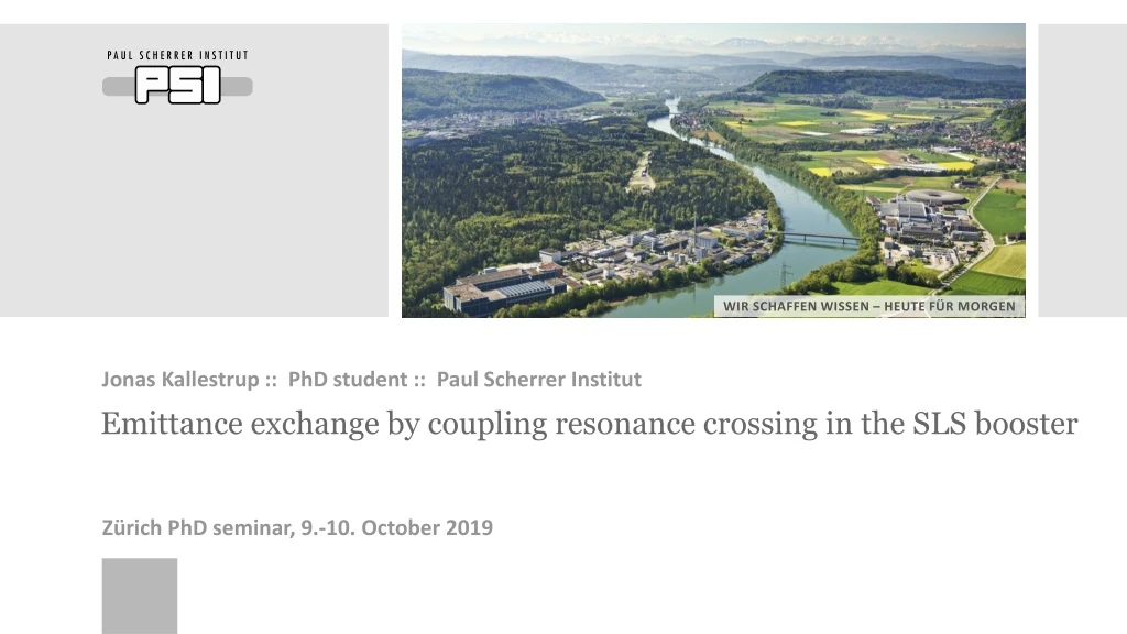
Jonas Kallestrup :: PhD student :: Paul ScherrerInstitut Emittanceexchangebycouplingresonancecrossing in the SLS booster Zürich PhDseminar, 9.-10. October 2019
Motivation • The Swiss Light Source (SLS) is a circular electron accelerator for production of synchrotron radiation for users of many disciplines of physics, chemistry, biology and more. • Electron beam energy: • Radiation spectral range: from UV (10 eV) to hard x-rays (35 keV) • A major upgrade of SLS is planned in order to provide radiation of even higher intensity • New “storage ring” accelerator with stronger focusing of the electron beam
The accelerator complex consists of: • Linear accelerator (linac): • Booster synchrotron: • Storage ring: • The current injector system will remain basically unchanged after the upgrade • Only a new storage ring will be built
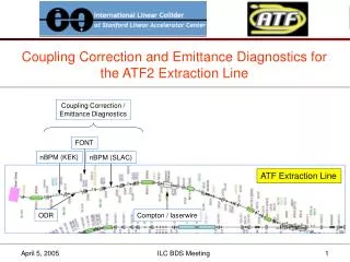
SLS booster: overview Storage ring Booster synchrotron
Motivation New accelerator design imposes new challenges that must be solved! • New ideas are put to use to make the photon beam more intense for SLS 2.0 • More and shorter magnets • ~900 magnets for SLS 2.0 instead of 336 for SLS • Stronger focusing • 72 T/m for SLS 2.0 instead of 20 T/m for SLS • Innovative accelerator design • “anti-bends” • “longitudinal gradient bends” • high-field, superconducting “super-bends” • A factor 30 higher brightness of radiation compared to SLS!
Challenges.. Physical aperture (vacuum chamber) Stored electron beam Ideal dynamic aperture Dynamic aperture including machine errors • Physical aperture • Vacuum chamber of the accelerator • Typically Ø20 mm for next generation of machine (approx. same diameter as 10 Rappen coin!) • Ideal dynamic aperture • Stable region of particle motion • Limited by strong non-linear magnets • Dynamic aperture including machine errors • Deteriorated stable region of particle motion due to magnet errors, misalignments etc. • Challenge: Injection more particles into the stable regionwithout kicking out the stored beam
Injection into storage rings 2 1 3 Stored beam Injected beam • Conventionalinjectionsusethe „kicker-bump“ scheme • The stored beam ispushedclosetothe wall of a „septummagnet“ usingtwo „kicker-magnets“ • The injected beam comes in on theothersideoftheseptum-wall • Twootherkicker-magnets pushesbothstored- andinjected beam back towardstheaxis • Injected beam must bewithindynamicapertureafter the last kicker-magnet; otherwisethey will get lost! Issue: Injected beam tendstobequitebigand (horizontal) dynamicaperturequitesmall..
Decreasing beam size (for zero dispersion) • Goal: decrease beam sizeofinjected beam! • For a gaussian beam distribution, the 1-sigma sizeis • canbethoughtof a measureofthe „focusing“ ofthe beam andis a functionoflong. positions. • Optimum valueofisfixed: Wedon‘tgainbydecreasing • : areaof beam phasespace: theemittance. • canbethoughtofasthe„temperature“ ofthebeam • Forelectronsynchrotrons: • Todecrease a new (andoftenbigger) accelerator must bebuilt • But! Emittancecanbetransferedfrom horizontal tovertical plane bycouplingthe beam transversely
Energytransferthroughcoupling Creator “YouLab”: https://www.youtube.com/watch?v=3c73d5GJ2V0 • Classicalphysicswithtwocoupledpendulums • Not exactlythe same, but yougettheidea!
Emittancetransferthroughcoupling A full emittance exchange between x-y can be done by gradually changing the particle oscillation frequency in one axis to cross the oscillations frequency in the other axis In accelerator-lingo, this is known as “emittance exchange by coupling resonance crossing” : number of beam oscillations per revolution (“tune”) : separation of fractional part of the tunes. is an integer : Couplingcoefficient– a measureofthe plane coupling,arisingfromskewquadrupolecomponents The emittancescanbeexchangedbylettinggofrom positive to negative.
Measurementsof beam oscillationfrequency: «tune» : number of beam oscillations per revolution : Couplingcoefficient • Nowweneedtoknow • Whatis, andtherebyofthebooster? • Whatis |C| ofthebooster? • is thenumberofoscillations per turn. • Fractionalpartcanbemeasured! • „Kick“ the beam • Measure beam positionevery turn • FFT ofmeasuredpositions
Measurement oftransverse plane coupling : number of beam oscillations per revolution : Couplingcoefficient =|C| Waterfall plot of many FFTs • OK! • Nowwehaveandtherefore • We still need |C|. • For a coupledsystem, themeasuredfrequenciesare not identicalto and . Instead, the normal modetunes, and aremeasured • Whencouplingispresent: • Couplingismeasuredusingthe„closest tune approach“ • Slightmodificationsoffocusing => changesfrequencies • Find minimumseparationofoscillationfrequencies |C| = 0.0192
Howto do theresonancecrossing Waterfall plot of many FFTs simulation • Almostthere: nowwehavetoactuallydo theresonancecrossing • i.e. quicklychangingoneofthetunestocrosstheother • Due toradiativeeffects, thecrossing must bedonequickly: ~ 1-3 ms • Beam must extractedtothestorage ring immediately after • Small decrease in quadrupolemagnetcurrent (~5A) duringthe last ~2500 turns (~2.5ms) ofmagnetramp
Results Beam focusing adjusted for clarityNot normal operation conditions Beam extraction Beam sizemeasured in the „Booster-to-Ring Transfer Line“ using an opticaltransitionradiationscreen Emittance Exchange process measured by extracting at earlier times over many ramp cycles
Results Beam focusing adjusted for clarityNot normal operation conditions Beam sizemeasured in the „Booster-to-Ring Transfer Line“ using an opticaltransitionradiationscreen Emittance Exchange process measured by extracting at earlier times over many ramp cycles
Results Beam focusing adjusted for clarityNot normal operation conditions (under normal operation conditions) • Beam sizemeasured in the „Booster-to-Ring Transfer Line“ using an opticaltransitionradiationscreen • Emittance Exchange process measured by extracting at earlier times over many ramp cycles • First Emittance Exchange for electron synchrotron successfully achieved: • I.e. a factor 2 reductionin horizontal beam size
Summary & outlook • New synchrotron light sourceprojectssufferfromsmall beam stabilityregions • Injections will behardwithtodaysboostersynchrotrons • Usingtransverse beam couplingandresonancecrossing, wehavedecreased/increasedthe horizontal/vertical beam sizeby a factor 2 • The SLS booster is a verygood booster with low horizontal emittance from design (10 nm.rad). • Other boosters have horizontal emittance in the order of 100 nm.rad or more • Apply emittance exchange will lead to a factor >10 decrease in ! • Emittance exchange is currently being considered in context of accelerator upgrade projects in Italyand France.
Summary & outlook Thankyouforyourattention!
Radiativeeffects An optimum between fast crossing, radiation damping and adiabatic exchange must be found • When beam emittances are “out of equilibrium”, the synchrotron radiation emission and quantum excitation will attempt to restore equilibrium • Emittance exchange is a dynamic process • Radiative effects play a role after the resonance crossing • Effect of emittance exchange is gradually lost • This means that the Emittance Exchange process must be fast • Fast quadrupole power supplies • But not too fast either! • Exchange must be adiabatic
Crossingspeeddependency • Consequences of low coupling: mismatch of emittance • If coupling is small, then a longer crossing time is needed to do a proper emittance exchange without mismatch of the emittance. • If crossing time is too short, the emittance exchange becomes nonadiabatic. • If crossing time is too long, radiation damping & quantum excitation will play a role. • Skew quadrupoles might be needed if coupling is too small.
Emittanceredistribution: exchange Δ: betatron tune separation |C|: coupling coefficient • A complete exchange of transverse emittances can be achieved by crossing the coupling resonance • Observed at the Proton Synchrotron (2001) • WhenΔ decreases, decreases, increases • WhenΔ = 0, = • When Δincreases on the other side of the resonance
Tune along ramp Goals: • Cross thecouplingresonancequicklytoachievetheemittanceexchange • Extract beam shortly after toavoiddamping Waterfall plot of FFT of Turn-by-Turn BPM data
Tune along ramp Goals: • Cross thecouplingresonancequicklytoachievetheemittanceexchange • Extract beam shortly after toavoiddamping Waterfall plot of FFT of Turn-by-Turn BPM data
Tune along ramp Goals: • Cross thecouplingresonancequicklytoachievetheemittanceexchange • Extract beam shortly after toavoiddamping Waterfall plot of FFT of Turn-by-Turn BPM data
Results • Test of injections with limited aperture by inserting horizontal scraper • Scraper can be inserted further without loss of charge when using emittance exchange • Fitting Cumulative Distribution Function