Download
1 / 61
620 likes | 725 Views
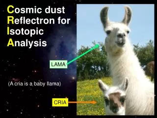
C osmic dust R eflectron for I sotopic A nalysis (CRIA). Critical Design Review September 26, 2007. Laura Brower: Project Manager Drew Turner: Systems Engineer Loren Chang Dongwon Lee Weichao Tu. Agenda. Organization System Design & Requirements Subsystem Design Test Plan

E N D
Cosmic dust Reflectron for Isotopic Analysis (CRIA) Critical Design Review September 26, 2007 Laura Brower: Project ManagerDrew Turner: Systems EngineerLoren ChangDongwon LeeWeichao Tu
Agenda • Organization • System Design & Requirements • Subsystem Design • Test Plan • Project Management Plan
Organizational Structure Customer Z. Sternovsky Administration System Engineer Project Manager L. Brower Student Lead D. Turner CU AdvisorsX. Li S. Palo ProfessionalM. Lankton (LASP) P. Graf Manufacturing Structures Thermal Electronics Student LeadD. Turner Student LeadL. Brower Student LeadW. Tu Student Lead B. Hodgkinson N. Little Professional S. Steg (LASP) Professional B. Lamprecht (LASP) Professional V. Hoxie (LASP) Professional M. Rhode (CU) Materials Ion Optics Detector Student LeadD. Lee Student LeadL. Chang Student LeadD. Turner Professional G. Drake (LASP) Experienced Graduate K. Amyx (CU) Professional G. Drake (LASP)
Agenda • Organization • System Design & Requirements • Subsystem Design • Test Plan • Project Management Plan
Supporting Electronics System Level Diagram Thermal Control Line Key Power High Voltage Heat Data • High voltage supply • Oscilloscopes • Computer • Power source • Heaters • Thermocouples Structure (Gray area) Mass Analyzer Instrument Electronics • Charge Sensitive Amplifier • Voltage dividers Ionizer Analyzer Detector (Target) • Annular electrodes • Ring electrodes • Grounded grids
Minimum Success Criteria • Achieve working instrument with mass resolution of at least 100 m/Δm (Req: 1.TR2) • Achieve TRL-5: Working prototype tested in relevant environments (Req: 1.TR4) Key Build/Test Phase Requirements 1. Meet assembly tolerances 2. Hardware budget < $30k 3. Cleanliness reqs for Vac chambers 4. Electronics accuracy Flowdown?
Agenda • Organization • Background • System Design & Requirements • Subsystem Design • Project Management Plan
Analyzer Thermal Structures Detector Ionizer Electronics/CDH Structural Design Fabrication Plan Structures Subsystem Lead: Drew Turner Speakers: Drew Turner, Dongwon Lee Assembly Plan
Hexagonal Structure: Overall Characteristics 10 *Not including instrument-spacecraft interface *All blind fasteners will be vented
Main Housing Assembly Assemblies Annular Electrode Assembly Target Assembly Detector Assembly
Structure Materials • Al T-6061 used for all metal parts • Noryl used for all insulator parts • Stainless steel fastners used with helicoils for small holes
Wiring Channel (Noryl) Annular Electrode Mount Annular Electrodes (BeCu 17200) Annular Electrode Standoff (Noryl) Annular Electrode Assembly
Inner/Outer Target Electrode Standoffs (Noryl) Grounded Grid Silver Coated Target Hexagonal Base Inner/Outer Target Electrodes Target Assembly
Detector Lid Top/Bottom Detector Grid Clamp Detector Detector Grid Detector Housing Cylinder Detector Assembly Del Mar (Insulation)
Main Assembly Main Housing Assembly Detector Assembly Target Assembly Annular Electrode Assembly
High Voltage – Ion Optics Heater/CSA Cable Layout
Mechanical Ground Support Equipment Interfaces • Remove-before-flight cover • Thermal Vacuum/Vibration Adapter Plate Put CRIA on its side in TVAC
Integration &Testing Features • Removal of Detector Assembly for Storage • Electrical / Soldering Access • Reconnecting the CSA • Panel removal for internal access
Fabrication/Assembly Schedule Outsourced Built In-House Assembly
In-House Manufacturing Schedule • 5 new undergraduates recently recruited • 2 new undergraduate machinists hired (UROP funding) • Working with DANDE to avoid conflicts in ASEN shop
Analyzer Subsystem Lead: Loren Chang Speakers: Loren Chang Analyzer Thermal Structures Detector Ionizer Electronics/CDH Voltage Divider Design
Analyzer: Requirements Updates?
Voltage Dividers (VD) • Converts 6 kV input ( µA) to voltages required for each electrode, as well as the target. • Precise values assembled from discrete resistors. Electrodes must be held at 0.5% prescribed values. • Design leaves space for additional corrector resistors.
VD PCB Design • Dimensions: 6.8 x 5.55”. • 2 layer FR4 board with 20 mil traces. 93 mil thickness (no breakdown issues). • Total power draw: 0.78 W. • Minimum component separation of 100 mils (larger for most components). • Wires to resistors to be connected via terminal posts. • PCB to be outsourced for etching. Soldering will be performed by team. • Entire board will be potted once assembly is complete. Pot with EN-4 and EN-11, potentially get from LASP?
VD Enclosure Design Aluminum box with cutouts on sides to allow wire passage • VD system uses DC. Shielding is not necessary. • Dimensions approx.: 7 x 5.75”. • Will be manufactured in house. Board mounted to enclosure using 4 x 0.118” screws on standoffs
Electronics Schedule Put into excel
Analyzer Thermal Structures Detector Ionizer Electronics/CDH Electronics Design CSA Layout/ Assembly Testing Electronics/CDH Subsystem Lead: Weichao Tu Speakers: Weichao Tu
CSA Subsystem Assembly • CSA: A250F/NF (2) • FET: SK152 (2) • Board: PC250F (2) PC250F Layout A250F/NF Connection
Functional Test Test Circuit • Soldering A250F/NF, FET • Function-test with • A pulser • Transition time < 20 ns • Step: 22 mV • A test capacitor • 2 pF • 22 mV step into 2 pF simulates the charge generated in a silicon detector by a particle losing 1MeV • Measure the output • Noise Measurement • Test with • A post amplifier • MCA or RMS Voltmeter
Dimensions: 1 X 2 X 3 inches Assemble into CSA Box Updates?
Triggering Test • Object: To test the combined triggering signals from the target and the grounded grid • Test Procedure • Connect one CSA to the target, the other CSA to the grounded grid • CSA Noise Floor Test • Connect the output signal to a Post-Amp and MCA/RMS voltmeter • Record the change of noise with temperature • Triggering Test • Laser-simulated impact • To determine whether resulting signals are detectable above the noise floor • Record the S/N and its change with temperature
Thermal Subsystem Lead: Laura Brower Speakers: Laura Brower Analyzer Thermal Structures Detector Ionizer Electronics/CDH Target Heater Design Heater Locations
Thermal Requirements Updates?
0.1” Al target substrate 0.5 mm Target Kapton FN (Kapton type: 150FN019) Minco Heater Target Heater Configuration • The heater is wrapped in a thin Kapton coating • An additional layer DuPont Kapton FN (Kapton type: 150FN019) provides the electrical insulation sufficient to shield the heater from the target at 5 kV. Where purchase from/cost?
Heater Locations • Heater location on electronics has not been analyzed Location 1: underneath target substrate Location 2: on Voltage Divider box
Agenda • Organization • Background • System Design & Requirements • Subsystem Design • Test Plan • Project Management Plan
Meeting Requirements through Testing TRL 5: test CRIA in a relevant environment • Performance reqs • Analysis (thermal, ion optics, electronics) • Test Plan/ Verification