Download
1 / 10
100 likes | 232 Views
Computer System Laboratory. Lab10 - Sensor II. Experimental Goal. Learn how to write programs on the PTK development board (STM32F207). Light Sensor. LCD. Key buttons. LED lamps. 7 segment LED. Joystick. Temperature Sensor. Environment. Host System Windows XP Build System

E N D
Computer System Laboratory Lab10 - Sensor II
Experimental Goal • Learn how to write programs on the PTK development board (STM32F207). Light Sensor LCD Key buttons LED lamps 7 segment LED Joystick Temperature Sensor / 10
Environment • Host System • Windows XP • Build System • VirtualBox + Ubuntu 8.04 • Target System • PTK development board (STM32F207) • Software • Documentation & examples • IAR Embedded Workbench • You can download all software from RSWiki CSL Course Software / 10
Introduction to PTK Development Board • STM32F207 is a SoC consisting of a Cortex-M3 Core, built-in flash storage, and many other peripherals. • The core can run up to 120MHz. • The on-chip memory includes a flash of 256KB and a SRAM of 128KB. • Cortex-M3 processors are a family of 32-bit ARM-based processors for highly deterministic real-time applications. • It implements the ARMv7-M architecture. • Nested Vectored Interrupt Controller (NVIC), Memory Protection Unit (MPU), … • It has 3-stage pipeline supporting Thumb/Thumb-2 ISA. / 10
Memory Mapping • The address space of STM32F207is split into eight 512MB blocks. • Block 0 maps the flash memory. • Block 1 maps the main memory. • Block 2 maps MMIO for peripherals. • Block 3/4 maps external devicesusing static memory interface. • Block 5 maps control registers ofthe flexible static memory controller(FSMC). • Block 7 maps internal registers ofthe processor core. / 10
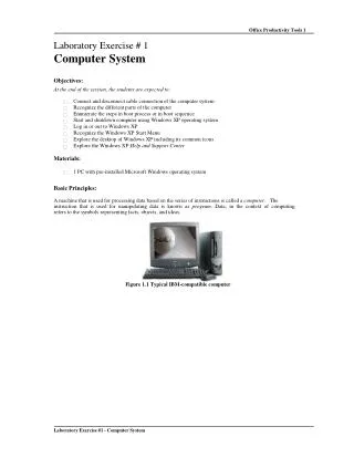
Hardware Connection DC Power RS-232 (COM Port) JTAG Debugger / 10
IAR Embedded Workbench • It is a commercial IDE for ARM-based SoCs. • Please use IAR Embedded Workbench for ARM 6.60, instead of 6.40. / 10
Building and Running (1/2) • Step 1: download the examples PTK_Examples.zip on Windows XP. • Step 2: download the Jlinkdriver, and install it. • Step 3: open the serial console, i.e., putty. • Please set baud rate to 115200bps. • Step 4: open the following workspace in IAR Embedded Workbench IDE. • PTK_Examples\ePBB\Applications\Projects\PTK-STM32F207\EWARM-V6\OS_None\base_uart\demo.eww / 10
Building and Running (2/2) • Step 5: compile the project by clicking the button “Make”. • Step 6: download the program to the target by clicking the button “Download and Debug”. • Step 7: press the key “F5” to continue the execution. • You will see the message “Hello World!!!” on the console. / 10
Lab Requirement • Show the current temperature and luminous flux on the UART console. • See …\OS_None\base_temperature\demo.eww and …\OS_None\base_light\demo.eww as a reference. • Hint • The documentation of these examples can be found at PTK_Examples/ePBB/Documentations. • You might add some driver sources into your project file. • Please send your report to both TAs. • csiedatou@gmail.com, meenchen79@gmail.com • Please use this title format: [CSL] G# Lab# Ver# • E.g., [CSL] G13 Lab9 Ver1 / 10