Download
1 / 15
150 likes | 303 Views
III. Water Treatment Technologies Topic. III. 5. Micro-mesh Screens. Filters: Kinds, Constructions and Operation. Micro-mesh Screens I. Purpose For plankton removal For colour removal II. Efficiency restriction Phytoplankton content - up to 10 6 cells/l

E N D
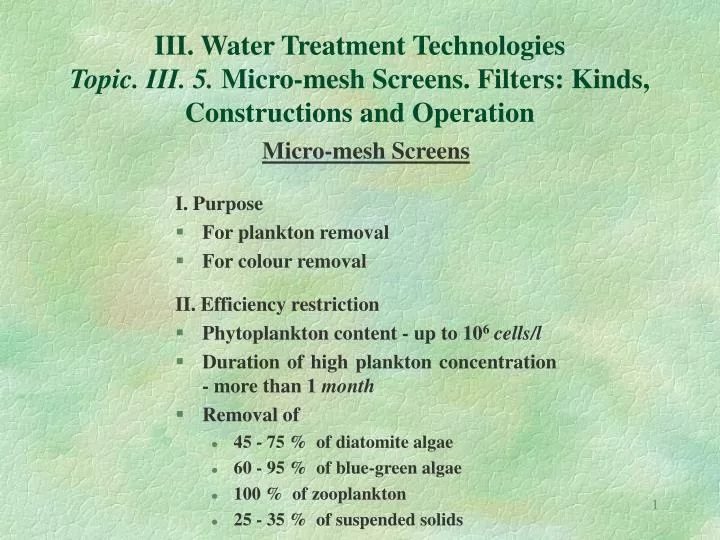
III. Water Treatment TechnologiesTopic. III. 5. Micro-mesh Screens. Filters: Kinds, Constructions and Operation Micro-mesh Screens I. Purpose • For plankton removal • For colour removal II. Efficiency restriction • Phytoplankton content - up to 106cells/l • Duration of high plankton concentration - more than 1 month • Removal of • 45 - 75 % of diatomite algae • 60 - 95 % of blue-green algae • 100 % of zooplankton • 25 - 35 % of suspended solids
Filters Kinds: I. According to the filtration rate • Low rate - 0,1 - 0,3 m/h • High rate - 5 - 10 (15) m/h • Super high rate - 50 m/h II. According to the filter layers • One-layer • Two-layers • Multy-layers III. According to the filter media • Sand (quartz) filters • Coal/sand filters • Ceramic filters • Ceramic/sand filters
Filters Kinds: IV. According to construction • Open (non-pressure) • Closed (pressure) • Vertical • Horizontal V. According to impurities removal mechanism • Coagulation/sorption • Ion exchange VI. According to reagents application • Without reagents’ treatment • With preliminary coagulation • With contact coagulation
Classical structure (Longitudinal Section) 1 - flowrate regulator; 2 - weir; 3 - inlet distribution channel; 4 - drainage pipe; 5 - filtered water pipe Low Rate Sand Filters
Low Rate Sand Filters Particularities: • Capacity limits • Water quantity < 1000 (5000) m3/d • Turbidity < 50 mg/l • Colour < 30 - 40 grad • Filtration duration - 20 - 30 d • Sand grains diameter def = 0,3 - 1 mm • Sand layer height h = 0,8 - 1 m • Water layer height H = 1,2 - 1,5 m • Filtration rate v = 0,1 - 0,3 m/h
Low Rate Sand Filters Particularities: • Filtering total capacity - Ktot Ktot = Kb + Knet , g/m2 Ktot = 2000 - 10000 g/m2; Kb - biofilm development capacity, g/m2; Kb = M.v0.Tb; Kb = 100 - 300 g/m2; Knet - net filtering capacity, g/m2; Knet = M.v0.Tnet M - coarse water turbidity, mg/l; v0 - filtration rate during period Tb , m/h; v0 = 0,05 - 0,1 m/h; Tb - biofilm development duration, h; Tb = 3 - 12 h at M > 100 mg/l; Tb = 24 - 36 h at M < 100 mg/l;
Low Rate Sand Filters Particularities: • Filtering total duration - Ttot Ttot = Tb + Tnet +Tw , h Tb - biofilm development duration, h; (time to reach bacteria concentration less than 100 numbers per cm3 and filtrate turbidity less than 2 mg/l); Tnet - net filtering duration, h; Tnet = (Ktot - Kb)/v; Tnet = 500 h; Tw - filter washing duration, h; Tw = 6 - 24 h
Scheme of Open Air Structure 1 - coarse water inlet pipe; 2 - washing water inlet pipe; 3 - filtered water pipe; 4 - wash water pipe; 5 - wash water drain channel; 6 - distribution pipes; 7 - supporting layer; 8 - filtering layer; 9 - wash water outflow channel High Rate Sand Filters
Scheme of Construction and Operation a - normal operation б - washing 1 - filtering layer; 2 - drainage (support) layer; 3 - distribution channel; 4 - distribution (wasout) channels; 5 - drainage system High Rate Sand Filters
Scheme and Operation Mode of Filtering Regulator h1- initial filtering head loses; h2- operational (decreasing) filtering head loses; H - total filtering head loses (H = h1 + h2 = const.); E - constant water level High Rate Sand Filters
Structure of Pressure High Rate Sand Filter 1 - coarse water inlet pipe; 2 - filtered water outlet pipe; 3 - wash water inlet pipe; 4, 5, 10 - stop valves; 6 - drainage (support) plate; 7 - filtering layer; 8 - supporting layer; 9 - wash air inlet pipe; 11 - manometer High Rate Sand Filters
Particularities: Capacity limits Water quantity -unlimited Turbidity < 25 mg/l Colour < 25 grad Filtration duration - 12 - 24 h Sand grains diameter def = 0,5 - 2 mm Sand layer height h = 0,8 - 1,2 m Water layer height H = 1,5 - 2 m Filtration rate v = 5 - 10 (15) m/h High Rate Sand Filters
High Rate Sand Filters Particularities: • Back-washing parameters • Wash water intensity - 6 - 8 l/s.m2 • Wash air intensity - 15 - 20 l/s.m2 • First stage water/air washing duration - 4 - 5 min • Second stage water washing duration - 3 - 4 min • Post-washing filtration • Duration - 10 - 12 min • Filtrate wasted to the sewer • Washing water quantity • 1 - 3 % of the water treatment plant capacity • Number of spare filtering cells (under reparation) • 5 - 10 % of number of the constructed ones