Download
1 / 17
170 likes | 333 Views
Design of Gridded-Tube Structures for the 805 MHz RF Cavity. Department of Mechanical, Materials, and Aerospace Engineering M. Alsharoa (PhD candidate) Fermilab Accelerator PhD Program. Advisors:. Illinois Institute of Technology: Dr. Gosz M (MMAE) Dr. Nair S (MMAE)

E N D
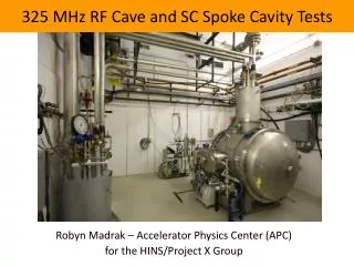
Design of Gridded-Tube Structures for the 805 MHz RF Cavity Department of Mechanical, Materials, and Aerospace Engineering M. Alsharoa (PhD candidate) Fermilab Accelerator PhD Program Advisors: • Illinois Institute of Technology: • Dr. Gosz M (MMAE) • Dr. Nair S (MMAE) • Dr. Kaplan D (BCPS) • Fermilab: • Dr. Moretti A. (Beam Division)
I. OBJECTIVE AND WORK PLAN • Work objective is to select the optimal combination of the design variables of the gridded-tube structure for the 805 MHz cavity with the constraints that stresses and out-of-plane deflection (design requirements) remain within the acceptable limits. • Design variables: • tube outer diameter • wall thickness • grid spacing if the grids are far a part or method of contact if they are at a close distance • number of grids • gap between tubes in a grid • distance between gridded-tube structures • type of coolant flowing inside the tubes • coolant flow rate Fig. 1 Two gridded-tube structures inside an RF cavity
The electromagnetic radiation inside the cavity will be modeled to obtain the heat flux loads acting on the gridded-tube structure. Forced convection due to coolant passage through the tubes will be considered. Then, heat transfer analysis will be performed to obtain the detailed temperature distribution inside the tubes. Then, thermal stress analysis will be performed. • First step in the modeling of the electromagnetic radiation inside the 805 MHz cavity is to perform Modal high frequency analysis of the cavity without considering the gridded-tube structures. Then, the effect of the gridded-tube structures will be considered.
II. INTRODUCTION • The governing equation of the propagation of the electromagnetic waves in a hollow cylinder made of a perfect conductor material and filled by a lossless dielectric is given by: • Boundary conditions: : permeability of the dielectric material (H/m) : permittivity of the dielectric material (F/m) : frequency (rad/sec), E: electric field (V/m) B : magnetic flux density (T) • The fields divide themselves into two categories: Transverse Magnetic (TM) waves where Transverse Electric (TE) waves where
III. MODELING OF AN 805 MHZ CYLINDRICAL SYMMETRIC PILLBOX CAVITY USING ANSYS • A right circular cylindrical cavity (cylindrical symmetric pillbox cavity) made of copper with a vacuum inside is modeled as a sample problem • The lowest TM mode has m = 0, n = 1 and p = 0 (TM010) • The resonance frequency of the TM010 is given by: • Vacuum permeability ( ) = e-7 H/m • Vacuum permittivity ( ) = 8.854 e-12 F/m • Cavity radius (R) is chosen so that the resonant frequency (f) = 805 MHz • Cavity gap (d) is chosen so that the volume equals the volume of the 805MHz cavity • R = 14.255 cm • d = 7.794 cm Fig. 2 Description of the 805 MHz cylindrical symmetric pillbox cavity
The Exact solution of the electric field inside the cavity is given by: • The Exact solution of the magnetic field inside the cavity is given by: • The quality factor of the cavity (Q) is defined as: • (Stored energy/Power stored) is the permeability of the wall of the cavity (copper) = e-7 H/m is the conductivity of copper = 5.882e8
Mesh Parameters: • Element type: Tetrahedral Elements (HF119) • Number of elements (Full mode): 125,000 • Number of elements (Quarter of the full model): 125,000 • The quarter of the full model is modeled to reduce the problem size. The symmetry planes are left without any boundary treatment. This allows ANSYS to assume perfect magnetic conductor condition at the symmetry planes (Ht= 0) which can be used as symmetry boundary conditions. • Simulation Results Full model Resonant frequency: 805 MHz Quality factor (dielectric loss): 0.0 Quality factor (surface loss): 21587.4871 Quality factor: 21587.4871 Quality factor relative error: 0.06% Quarter of the full model Resonant Frequency: 805 MHz Quality factor (dielectric loss): 0.0 Quality factor (surface loss): 21605.0391 Quality factor: 21605.0391 Quality factor relative error: 0.02%
Fig.3 Normalized electric field inside the 805 MHz cylindrical symmetric pillbox cavity versus the radius of the cavity
Fig. 4 Contour plot of the magnitude of the electric field Fig.5 Vector plot of the electric field
Fig. 6 Contour plot of the magnitude of the magnetic field Fig.7 Vector plot of the magnetic field
Fig. 8 Contour plot of the magnitude of the electric field Fig. 9 Vector plot of the electric field Fig. 11 Vector plot of the magnetic field Fig. 10 Contour plot of the magnitude of the magnetic field
IV. MODELING OF THE 805 MHZ LBNL HIGH POWER TEST CAVITY • MAFIA simulation results* • Frequency: 805 MHz • Quality factor: 18,800 • Modal high frequency analysis is performed. This includes meshing the internal volume of the cavity that is between the two-beryllium foils, applying the boundary conditions and excitation, and solving for the resonant frequency, electric and magnetic fields inside the cavity and the quality factor. Fig. 12 Cross-sectional view of the 805 MHz LBNL high power test cavity *D. Li, “805 MHz Pillbox Cavity”, MUCOOL/MICE meeting, IIT, Chicago, IL, Feb. 2002
: conductivity of beryllium = 23255813.95 : permeability of beryllium = e-7 H/m. • Quarter of the 805 MHz cavity model is considered to reduce the problem size • Element type: Tetrahedral Elements (HF119) • Number of elements: 120,000 • Simulation Results: • Frequency: 808.322 MHz compared to 805 MHz • Frequency relative error: 0.41% • Quality factor (dielectric loss only): 0.0 • Quality factor (surface loss only): 18641.558 • Quality factor: 18641.558 compared to 18,800 • Quality factor relative error: 0.84% • The results agree very well with the MAFIA simulations. The MAFIA simulations included a coupling slot on the cavity which was not considered in the current simulation. That explains why the frequency obtained is higher.
Fig. 13 Contour plot of the magnitude of the electric field Fig. 14 Vector plot of the electric field
Fig. 15 Contour plot of the magnitude of the magnetic field Fig. 16 Vector plot of the magnetic field
V. MESHING A SAMPLE GRIDDED- TUBE STRUCTURE • The sample model contains two perpendicular touching tubes inside a right circular cylinder. The mesh is composed of tetrahedral elements. The following figures illustrate the meshing steps needed to mesh the gridded-tubes and the surrounding volume. Fig. 17 Meshing steps of a sample gridded-tube structure Electromagnetic modeling: removing tube elements and keeping tube surfaces and the surrounding volume. Thermal modeling: removing the surrounding volume of the tubes and keeping tube elements • Improved adaptive meshing techniques are needed for time efficient optimization of the design of the gridded-tube structure.
VI. PRESENT AND FUTURE WORK • Studying the mesh of the 805 MHz cavity with gridded-tube structures embedded inside the cavity. • High frequency analysis of the 805 MHz cavity with gridded-tube structures embedded inside the cavity (Collaboration with MUCOOLers from LBNL). • Calculating the heat flux loads acting on the gridded-tube structures and performing thermal stress analysis (interesting game). • Optimizing the design parameters of the gridded-tube structure.