Download

1 / 62
640 likes | 816 Views
Dimensioning Review. Dimensioning. Orthographic and Isometric Views define the shape and general features of the object Dimensioning adds information that specifies Size of the object Location of features (e.g. holes) Characteristics of features (e.g. depth and diameter of hole)

E N D
Dimensioning Review
Dimensioning • Orthographic and Isometric Views define the shape and general features of the object • Dimensioning adds information that specifies • Size of the object • Location of features (e.g. holes) • Characteristics of features (e.g. depth and diameter of hole) • Dimensions also communicate the tolerance (or accuracy) required
Some General Guidelines • Start by dimensioning basic outside dimensions of the object. • Add dimension for location and size of removed features • Add general and specific notes – such as tolerances
Dimensioning Basic Shapes – Assumptions • Perpendicularity • Symmetry
Dimensioning Shows: A) Size B) Location and Orientation • ALWAYS give DIAMETER • " " for full circles (360 degrees) and RADIUS "R" for arcs (less than 360 degrees)
Principles of Good Dimensioning • The overriding principle of dimensioning is CLARITY • Principles – not an infallible rule set, need to apply good judgment.
Each feature dimensioned once and only once Dimensions should suit the function of the object Principles of Good Dimensioning
Objectives • Understand description and control of variability through tolerancing • Understand various classes of fits • Introduce multiple part tolerancing
Tolerance Tolerance is the total amount a dimension may vary. It is the difference between the maximum and minimum limits. Ways to Express: • Direct limits or as tolerance limits applied to a dimension • Geometric tolerances • A general tolerance note in title block • Notes referring to specific conditions
ANSI/ASME Standard ANSI/ASME Standard Y14.5 Each dimension shall have a tolerance, except those dimensions specifically identified as reference, maximum, minimum, or stock. The tolerance may be applied directly to the dimension or indicated by a general note located in the title block of the drawing.
Variation is Unavoidable • No two manufactured objects are identical in every way. Some degree of variation will exist. • Engineers apply tolerances to part dimensions to reduce the amount of variation that occurs.
Tolerances Three basic tolerances that occur most often on working drawings are: limit dimensions, unilateral, and bilateral tolerances.
Tolerances Three basic tolerances that occur most often on working drawings are: limit dimensions, unilateral, and bilateral tolerances.
Limit Dimensions Limit dimensions are two dimensional values stacked on top of each other. The dimensions show the largest and smallest values allowed. Anything in between these values is acceptable.
Limit Dimensions These are limit dimensions, because the upper and lower dimensional sizes are stacked on top of each other.
Unilateral Tolerance A unilateral tolerance exists when a target dimension is given along with a tolerance that allows variation to occur in only one direction.
Unilateral Tolerance This tolerance is unilateral, because the size may only deviate in one direction.
Bilateral Tolerance A bilateral tolerance exists if the variation from a target dimension is shown occurring in both the positive and negative directions.
1. Direct Limits and Tolerance Values – Plus and Minus Dimensions
2. Geometric Tolerance System Feature Control Frame Geometric Dimensioning and Tolerancing (GD&T) is a method of defining parts based on how they function, using standard ANSI symbols. Concentricity Symbol AU 2008
3. Tolerance Specifications in Title Block General tolerance note specifies the tolerance for all unspecified toleranced dimensions. AU 2008
4. Notes Referring to Specific Conditions General Tolerances could be in the form of a note similar to the one shown below: ALL DECIMAL DIMENSIONS TO BE HELD TO .002" Means that a dimension such as .500 would be assigned a tolerance of 0.002, resulting in a upper limit of .502 and a lower limit of .498
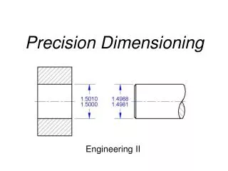
Important Terms – Single Part • Nominal Size – general size, usually expressed in common fractions (1/2" for the slot) • Basic Size – theoretical size used as starting point (.500" for the slot) • Actual Size – measured size of the finished part (.501" for the slot)
Important Terms – Single Part • Limits – maximum and minimum sizes shown by tolerances (.502 and .498 – larger value is the upper limit and the smaller value is the lower limit, for the slot) • Tolerance – total allowable variance in dimensions (upper limit – lower limit) – object dimension could be as big as the upper limit or as small as the lower limit or anywhere in between
Important Terms – Multiple Parts • Allowance – the minimum clearance or maximum interference between parts • Fit – degree of tightness between two parts • Clearance Fit – tolerance of mating parts always leaves a space • Interference Fit – tolerance of mating parts always results in interference • Transition Fit – sometimes interferes, sometimes clears
Tolerance of B Fit Tolerance: Clearance or Interference Part B Tolerance of A Part A Fitting Multiple Parts AU 2008
Shaft and Hole Fits ClearanceInterference
CLEARANCE FIT+ .003 Shaft and Hole Fits Transition
Standard Precision Fits: English Units • Running and sliding fits (RC) • Clearance locational fits (LC) • Transition locational fits (LT) • Interference locational fits (LN) • Force and shrink fits (FN)
Basic Hole System or Hole Basis • Definition of the "Basic Hole System": The "minimum size" of the hole is equal to the "basic size" of the fit • Example: If the nominal size of a fit is 1/2", then the minimum size of the hole in the system will be 0.500"
SMAX SMIN HMAX HMIN Basic Hole System – G28-A • Clearance = Hole – Shaft • Cmax = H____ – S____ • Cmin = H____ – S____ Fill in the subscripts (min, max) in the equations above.
SMAX SMIN HMAX HMIN Basic Hole System • Clearance = Hole – Shaft • Cmax = Hmax – Smin • Cmin = Hmin – Smax Both Cmax and Cmin <0 – _________ fit Both Cmax and Cmin >0 – _________ fit Cmax > 0; Cmin < 0 – ___________ fit What types of fits are these? AU 2008
SMAX SMIN HMAX HMIN Basic Hole System • Clearance = Hole – Shaft • Cmax = Hmax – Smin • Cmin = Hmin – Smax Both Cmax and Cmin <0 – Interference fit Both Cmax and Cmin >0 – Clearance fit Cmax > 0; Cmin < 0 – Transition fit • System Tolerance = Cmax – Cmin • Allowance = Min. Clearance = Cmin AU 2008
.490 .485 .510 .505 Basic Hole System Calculate Maximum and Minimum Clearance Clearance = Hole – Shaft Cmax = Hmax – Smin Cmax = .510 – .485 = .025 Cmin = Hmin – Smax Cmin = .505 – .490 = .015 What type of fit is this? Cmax > Cmin > 0 Clearance
Metric Limits and Fits • Based on Standard Basic Sizes – ISO Standard • Note that in the Metric system: Nominal Size = Basic Size • Example: If the nominal size is 8, then the basic size is 8
Metric Tolerance Homework – TOL-1 Free Running H9/d9 Basic Size: 10 (1) Nominal Size: ? (1) Nominal Size: 10 ???? ???? 9.960 9.924 (2) Shaft Limits: (3) Shaft Tolerance: ???? (3) Shaft Tolerance: 0.036 (7) Minimum Clearance: ???? (8) Maximum Clearance: ???? (7) Minimum Clearance: 0.040 (8) Maximum Clearance: 0.112 ???? ???? 10.036 10.000 (4) Hole Limits: (5) Hole Tolerance: ???? (5) Hole Tolerance: 0.036 (6) Ts: ???? (6) Ts: 0.072 CHECK: Ts = Cmax – Cmin? CHECK: 0.072 = 0.112 – 0.040 = 0.072
Today's Assignment • Tolerance Yellow Packet • All problems. • Due 4/16
Objectives • Introduce Surface Control terms and symbols • Introduce Geometric Dimensioning and Tolerancing
Surface Control • Why do we need to control surface characteristics? • Rough surfaces cause friction and wear • It is difficult to make accurate measurements from rough surfaces
Surface Characteristics • Roughness • Small hills and valleys found on a surface • Defined as the arithmetic average of the deviations above and below a mean height of a surface • Expressed in microinches or micrometers.
Surface Characteristics • Waviness • Surface irregularities greater than roughness • Expressed in inches or millimeters • See Figure 7.21 on page 7-14 of TG • Lay • Direction of tool marks on a machined surface. • See Figure 7.20 on page 7-13 of TG.
.25 inches Surface Control Symbol .125 in Material removal not specified Material must be removed Material must not be removed Surface Texture Symbols Autumn 2009
Bar added Symbol location Lay Symbols Parallel to line representing surface Perpendicular to the line representing the surface Both directions to the line representing the surface Multidirectional marks Circular Radial Lay particulate, non-directional, protuberant M C R P