Download

1 / 103
1.41k likes | 2.19k Views
Chapter 5 – Flip-Flops and Related Devices. Chapter 5 Objectives. Selected areas covered in this chapter : Constructing/analyzing operation of latch flip-flops made from NAND or NOR gates. Differences of synchronous/asynchronous systems. Major differences between parallel & serial transfers.

E N D
Chapter 5 Objectives • Selected areas covered in this chapter: • Constructing/analyzing operation of latch flip-flops made from NAND or NOR gates. • Differences of synchronous/asynchronous systems. • Major differences between parallel & serial transfers. • Operation of edge-triggered flip-flops. • Typical characteristics of Schmitt triggers. • Effects of clock skew on synchronous circuits. • Troubleshoot various types of flip-flop circuits. • Sequential circuits with PLDs using schematic entry. • Logic primitives, components & libraries in HDL code. • Structural level circuits from components.
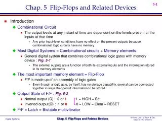
Chapter 5 Introduction • Block diagram of a general digital system that combines combinational logic gates with memory devices.
The flip-flop is known by other names,including latch and bistable multivibrator. Chapter 5 Introduction • The most important memory element is the flip-flop (FF)—made up of an assembly of logic gates.
When the latch is set: Q = 1 and Q = 0 • When the latch is clear or reset: Q = 0 and Q = 1 5-1 NAND Gate Latch • The NAND gate latch or simply latch is a basic FF. • Inputs are SET and CLEAR (RESET). • Inputs are active-LOW—output will change when the input is pulsed LOW.
In both cases, Q ends up HIGH. 5-1 NAND Gate Latch – Setting the Latch (FF) • Pulsing the SET input to the 0 state... • (a) Q = 0 prior to SET pulse. • (b) Q = 1 prior to SET pulse.
In each case, Q ends up LOW. 5-1 NAND Gate Latch – Resetting the Latch (FF) • Pulsing RESET LOW when... • (a) Q = 0 prior to the RESET pulse. • (b) Q = 1 prior to the RESET pulse.
NAND latch equivalent representationsand simplified block diagram. 5-1 NAND Gate Latch – Alternate Representations
SET = 0, RESET = 0—Tries to set and clear the latchat the same time, and produces • Output is unpredictable, and this input conditionshould not be used. Q = Q = 1. 5-1 NAND Gate Latch - Summary • Summary of the NAND latch: • SET = 1, RESET = 1—Normal resting state, outputs remain in state they were in prior to input. • SET = 0, RESET = 1—Output will go to Q = 1 and remains there, even after SET returns HIGH. • Called setting the latch. • SET = 0, RESET = 0—Will produce Q = 0 LOW and remains there, even after RESET returns HIGH. • Called clearing or resetting the latch.
Two cross-coupled NOR gates can be used as a NOR gate latch—similar to the NAND latch. • The Q and Q outputs are reversed. The SET and RESET inputs are active-HIGH.Output will change when the input is pulsed HIGH. 5-2 NOR Gate Latch
SET = 1, RESET = 1—Tries to set and reset the latchat the same time, and produces • Output is unpredictable, and this input conditionshould not be used. Q = Q = 0. 5-1 NOR Gate Latch - Summary • Summary of the NOR latch: • SET = 0, RESET = 0—Normal resting state, No effect on output state. • SET = 1, RESET = 0—will always set Q = 1, where it remains even after SET returns to 0. • SET = 0, RESET = 1—will always clear Q = 0, where it remains even after RESET returns to 0.
Chapter 5 • When power is applied, it is not possible to predict the starting state of a flip-flop’s output. • If SET and RESET inputs are in their inactive state. • To start a latch or FF in a particular state, it must be placed in that state by momentarily activating the SET or RESET input, at the start of operation. • Often achieved by application of a pulse to the appropriate input.
5-3 Troubleshooting Case Study Troubleshootthe circuit.
5-3 Troubleshooting Case Study • There are several possibilities: • An internal open connection at Z1-1, which would prevent Q from responding to the input. • An internal component failure in NAND gate Z1 that prevents it from responding properly. • Q output is stuck LOW, which could be caused by: • Z1-3 internally shorted to ground • Z1-4 internally shorted to ground • Z2-2 internally shorted to ground • The Q node externally shorted to ground
A positive pulse hasan active-HIGH level. 5-4 Digital Pulses Signals that switch between active andinactive states are called pulse waveforms.
A negative pulse hasan active-LOW level. 5-4 Digital Pulses Signals that switch between active andinactive states are called pulse waveforms.
Measured between the 10% and 90% pointson the leading edge of the voltage waveform. 5-4 Digital Pulses • In actual circuits it takes time for a pulse waveform to change from one level to the other. • Transition from LOW to HIGH on a positive pulse is called rise time (tr).
Measured between the 90% and 10% points on the trailing edge of the voltage waveform. 5-4 Digital Pulses • In actual circuits it takes time for a pulse waveform to change from one level to the other. • Transition from HIGH to LOW on a positive pulse is called fall time (tf).
The time between the points when the leading and trailing edges areat 50% of the HIGH level voltage. 5-4 Digital Pulses • In actual circuits it takes time for a pulse waveform to change from one level to the other. • A pulse also has a duration—width—(tw).
5-5 Clock Signals and Clocked Flip-Flops • Digital systems can operate either asynchronously or synchronously. • Asynchronous system—outputs can change state at any time the input(s) change. • Synchronous system—output can change stateonly at a specific time in the clock cycle.
Transitions arealso called edges. 5-5 Clock Signals and Clocked Flip-Flops • The clock signal is a rectangular pulse train or square wave. • Positive going transition (PGT)—clock pulse goes from 0 to 1. • Negative going transition (NGT)—clock pulse goes from 1 to 0.
A small triangle at the CLK input indicates that the inputis activated with a PGT. A bubble and a triangle indicates that the CLK inputis activated with a NGT. 5-5 Clock Signals and Clocked Flip-Flops • Clocked FFs change state on one or the other clock transitions. • Clock inputs are labeled CLK, CK, or CP.
5-5 Clock Signals and Clocked Flip-Flops • Control inputs have an effect on the output only at the active clock transition (NGT or PGT)—also called synchronous control inputs. • The control inputs get the outputs ready to change, but the change is not triggered until the CLK edge.
5-5 Clock Signals and Clocked Flip-Flops • Setup time (tS) is the minimum time interval before the active CLK transition that the control input must be kept at the proper level.
5-5 Clock Signals and Clocked Flip-Flops • Hold time (tH) is the time following the active transition of the CLK, during which the controlinput must kept at the proper level.
5-6 Clocked S-R Flip-Flop • The S and R inputs are synchronous control inputs, which control the state the FF will go to when the clock pulse occurs. • The CLK input is the trigger input that causes theFF to change states according to the S and R inputs. • SET-RESET (or SET-CLEAR) FF will change states at positive- or negative-going clock edges.
The S and R inputs control the state of the FF in the same manner as described earlier for the NOR gate latch, but the FF does not respondto these inputs until the occurrence of the PGT of the clock signal. 5-6 Clocked S-R Flip-Flop A clocked S-R flip-flop triggered by thepositive-going edge of the clock signal.
5-6 Clocked S-R Flip-Flop Waveforms ofthe operation ofa clocked S-Rflip-flop triggered by the positive-going edge of a clock pulse.
Both positive-edge and negative-edgetriggering FFs are used in digital systems. 5-6 Clocked S-R Flip-Flop A clocked S-R flip-flop triggered by thenegative-going edge of the clock signal.
5-6 Clocked S-R Flip-Flop – Internal Circuitry • An edge-triggered S-R flip-flop circuit features: • A basic NAND gate latch formed by NAND-3 and NAND-4. • A pulse-steering circuit formed by NAND-1 and NAND-2. • An edge-detector circuit.
The duration of the CLK* pulses is typically 2–5 ns. 5-6 Clocked S-R Flip-Flop – Internal Circuitry • Implementation of edge-detector circuits used in edge-triggered flip-flops: • (a) PGT; (b) NGT.
5-7 Clocked J-K Flip-Flop • Operates like the S-R FF. • J is SET, K is CLEAR. • When J and K are both HIGH, output is toggledto the opposite state. • May be positive going or negative going clock trigger. • Much more versatile than the S-R flip-flop, as it has no ambiguous states. • Has the ability to do everything the S-R FF does, plus operates in toggle mode.
5-7 Clocked J-K Flip-Flop Clocked J-K flip-flop that respondsonly to the positive edge of the clock.
5-7 Clocked J-K Flip-Flop Clocked J-K flip-flop that respondsonly to the negative edge of the clock.
5-7 Clocked J-K Flip-Flop – Internal Circuitry • The internal circuitry of an edge-triggered J-Kflip-flop contains the same three sections asthe edge-triggered S-R flip-flop.
5-8 Clocked D Flip-Flop • One data input—output changes to the value of the input at either the positive- or negative-going clock trigger. • May be implemented with a J-K FF by tyingthe J input to the K input through an inverter. • Useful for parallel data transfer.
5-8 Clocked D Flip-Flop D flip-flop that triggers only onpositive-going transitions.
5-8 Clocked D Flip-Flop - Implementation • An edge-triggered D flip-flop is implemented by adding a single INVERTER to the edge-triggered J-K flip-flop. • The same can be done to convert a S-R flip-flopto a D flip-flop. Edge-triggered D flip-flopimplementation from a J-K flip-flop.
5-8 Clocked D Flip-Flop – Parallel Data Transfer Outputs X, Y, Z are to be transferredto FFs Q1, Q2, and Q3 for storage. Using D flip-flops, levels present at X, Y & Z will be transferred to Q1, Q2 & Q3, upon application of a TRANSFER pulse to the common CLK inputs.
5-8 Clocked D Flip-Flop – Parallel Data Transfer Outputs X, Y, Z are to be transferredto FFs Q1, Q2, and Q3 for storage. This is an example of parallel data transfer of binary data—the three bits X, Y & Z are transferred simultaneously.
5-9 D Latch (Transparent Latch) • The edge-triggered D flip-flop uses an edge-detector circuit to ensure the output responds to the D input only on active transition of the clock. • If this edge detector is not used, the resultant circuit operates as a D latch.
5-9 D Latch (Transparent Latch) D latch structure, function table, logic symbol.
The common input to the steering gates is called an enable input (abbreviated EN)—rather than a clock input. • Its effect on the Q and Q outputs is not restricted to occurring only on its transitions 5-9 D Latch (Transparent Latch) • The circuit contains the NAND latch and the steering NAND gates 1 and 2 without the edge-detector circuit.
5-10 Asynchronous Inputs • Inputs that depend on the clock are synchronous. • Most clocked FFs have asynchronous inputs that do not depend on the clock. • Labels PRE & CLR are used for asynchronous inputs. • Active-LOW asynchronous inputs will have a bar over the labels and inversion bubbles. • If the asynchronous inputs are not used they will be tied to their inactive state.
5-10 Asynchronous Inputs Clocked J-K flip-flop with asynchronous inputs.
5-10 Asynchronous Inputs - Designations • IC manufacturers do not agree on nomenclature for asynchronous inputs. • The most common designations are PRE (PRESET) and CLR (CLEAR). • Clearly distinguished from synchronous SET & RESET. • Labels such as S-D (direct SET) and R-D (direct RESET) are also used.
5-10 Asynchronous Inputs A J-K FF that responds to a NGT on its clockinput and has active-LOW asynchronous inputs.
5-11 Flip-Flop Timing Considerations - Parameters • Important timing parameters: • Setup and hold times • Propagation delay—time for a signal at the input to be shown at the output. (tPLH and tPHL) • Maximum clocking frequency—Highest clock frequency that will give a reliable output. (fMAX) • Clock pulse HIGHand LOW times—minimum clock-time between HIGH/LOW changes.( tW(L); tW(H) ) • Asynchronous Active Pulse Width—time theclock must HIGH before going LOW, and LOWbefore going HIGH. • Clock transition times—maximum time for clock transitions, • Less than 50 ns for TTL ; 200 ns for CMOS
5-11 Flip-Flop Timing Considerations - Parameters FF propagation delays. Clock Pulse HIGH and LOW and Asynch pulse width.