Download
1 / 14
150 likes | 468 Views
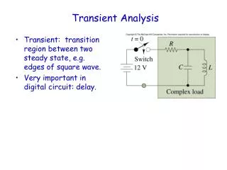
Transient signals. EE 2303. Overview. What is a TRANSIENT Signal ??? Recap Of OSCILLOSCOPE Switches and Terminology Review Of Logic gates Flip-Flop and Latches. What is a Transient Signal???.

E N D
Transient signals EE 2303
Overview • What is a TRANSIENT Signal ??? • Recap Of OSCILLOSCOPE • Switches and Terminology • Review Of Logic gates • Flip-Flop and Latches
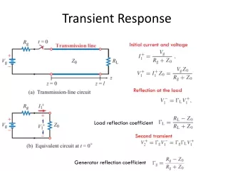
What is a Transient Signal??? • Signals which last for a very short period of time are referred to as “ TRANSIENT Signals”. • Examples: Switch bounce, Shock wave generated from an impact test, Seismic Signals..
Run Control Menu • Run/Stop (Green): Instrument is continuously acquiring data • Run/Stop (Red): Instrument has stopped Acquiring data • SINGLE : Instrument will wait for the user defined event (typically voltage set by the user)
Trigger Menu Trigger tells the oscilloscope when to start acquiring data. Normally edge triggering is done
Triggering modes • Normal mode: Displays a waveform when the trigger conditions are met. Used for very short signals (*****) • Auto mode: Displays a waveform when the trigger conditions are met. Used for all signals • Auto-level mode: can be used only when EDGE is selected on the front panel
Coupling Modes • DC Coupling : Allows both D.C. and A.C. signal to flow in to the trigger path. • AC coupling : Allows A.C only
Switches and Related Terminology • Pole - number of switch contact sets. • Throw - number of conducting positions, single or double. • Way - number of conducting positions, three or more. • Open - off position, contacts not conducting. • Closed - on position, contacts conducting, there may be several on positions.
Single pole Double Throw Switch(SPDT-Switch) SPDT can be “ON” in both positions, switching on a separate device in each case. It is often called a “change over switch”.
Flip-Flops and Latches • Flip-Flop and Latches are sequential circuits which are built from basic logic gates. • Flip-Flop and latches form the fundamental unit of “memory” in modern computers. • Each flip-flop can store 1 bit of information.
Basic Idea Of the Experiment View transient VOLTAGE SOURCE Remove transient VOLTAGE SOURCE