Download

1 / 49
500 likes | 804 Views
Failure Mode and Effect Analysis. By: Yuva Raj Siva Nick. Failure Mode and Effect Analysis. FMEA is a procedure in operations management for analysis of potential failure modes within a system for classification by severity or determination of the effect of failures on the system. Concept.

E N D
Failure Mode and Effect Analysis By: Yuva Raj Siva Nick
Failure Mode and Effect Analysis FMEA is a procedure in operations management for analysis of potential failure modes within a system for classification by severity or determination of the effect of failures on the system
Concept Rating, Analysis, Documentation Looking at problems before they are an issue Preventative maintenance Early detection
Benefits Captures the collective knowledge of a team Logical, structured process for identifying process areas of concern Documents and tracks risk reduction activities
Benefits Helps to identify Critical-To-Quality characteristics (CTQs) Provides historical records; establishes baseline Helps increase customer satisfaction and safety
Limitations Prioritizes but doesn’t’ correct Only as good as your team Time consuming Unknown Unknowns Scopes can become to large Operators can provide excessive issues Not updating the existing FMEA charts
History United States Military 1949 Aerospace and Rocket developmentSmall sample size & large costs Airplane and missile research Apollo 13
History Food service, plastics, health care Advanced Product Quality Planning Similar to six-sigma Ford Motor Company Pinto Scandal
Analyze • Determine to there is high risk of failure and determine if the failure are detectable • Improve • Evaluate impact of proposed changes • Control • determine which failure modes are the most critical to control –
SYTEM – focuses on global system function DESIGN- focus on components and subsystems PROCESS – focuses on manufacturing and assembly processes SERVICE – focus on service function. SOFTWARE – focus on software functions
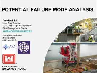
Back Ground Task for PFMEA (Process FMEA) 1. Details of the manufacturing process/Process flow chart 2. List of critical process parameters (Temperature, Pressure, etc.) 3. Properties of device material (brittleness, density etc.) 4. Manufacturing environment details 5. Manufacturing Tool details 6. Batch to batch variation
Detail design of Device • 2. Part/Component list • 3. Functions of components • 4. Theory/principle for the positioning of different components at their respective places (pin, sieve etc) • 5. Operating environment conditions (Humidity level, Pressure, Temp etc) • 6. Design Specifications (with Tolerances) • 7. Details of operating methods (pin movement fidelity, fatigue effects etc) • 8. Critical parameters of design and its dimensions Back Ground Task forDFMEA (Design FMEA)
Applications • FMEA is most commonly applied but not limited to design (Design FMEA) and manufacturing processes • (Process FMEA). • Design Failure Modes and Effects Analysis (DFMEA) identify potential failures of a design before they • occur. DFMEA then goes on to establish the potential effects of the failures, their cause, how often and • when they might occur and their potential seriousness. • Process Failure Modes and Effects Analysis (PFMEA) is a systemized group of activities intended to: • 1. Recognize and evaluate the potential failure of a product/process and its effect, • 2. Identify actions which could eliminate or reduce the occurrence, or improve detect ability, • 3. Document the process, and • 4. Track changes to process-incorporated to avoid potential failures.
Salient Features of FMEA • • First Time Right • Identifies inadequacies in the development of the product • • Test and trial may be limited to a few products • Regulatory Reasons • Continues Improvement • Preventive (not Corrective) Approach • Team Building • Required by Procedures
The FMEA is a living document. Throughout the product development cycle change and updates are made to the product and process. These changes can and often do introduce new failure modes. It is therefore important to review and/or update the FMEA when: • A new product or process is being initiated (at the beginning of the cycle). • Changes are made to the operating conditions the product or process is expected to function in. • A change is made to either the product or process design. The product and process are inter-related. When the product design is changed the process is impacted and vice-versa. • New regulations are instituted. • Customer feedback indicates problems in the product or process. Timing
The Language of FMEA Failure Mode Failure Effect Effect Analysis Failure Mode Analysis (FMA) Design FMEA Process FMEA
Risk assessment factors Security (S) 1= no effect 10= maximum severity Probability of occurrence (O) 1=very unlikely to occur 10= almost certain to occur Probability of Detection (D) 1= nearly certain detection 10= impossible to detect Risk Priority Number (RPN) RPN= S*O*D 1(virtually no risk)< RPN < 1000(extremely risk)
FMEA Procedure # Describe the product/process and its function. An understanding of the product or process under consideration is important to have clearly articulated. This understanding simplifies the process of analysis by helping the engineer identify those product/process uses that fall within the intended function and which ones fall outside. It is important to consider both intentional and unintentional uses since product failure often ends in litigation, which can be costly and time consuming. # Create a Block Diagram of the product or process. A block diagram of the product/process should be developed. This diagram shows major components or process steps as blocks connected together by lines that indicate how the components or steps are related. The diagram shows the logical relationships of components and establishes a structure around which the FMEA can be developed. Establish a Coding System to identify system elements. The block diagram should always be included with the FMEA form. # Complete the header on the FMEA Form worksheet: Product/System, Subsys./Assy., Component, Design Lead, Prepared By, Date, Revision (letter or number), and Revision Date. Modify these headings as needed.
# Complete the header on the FMEA Form worksheet: Product/System, Subsys./Assy., Component, Design Lead, Prepared By, Date, Revision (letter or number), and Revision Date. Modify these headings as needed.
# Identify Failure Modes: A failure mode is defined as the manner in which a component, subsystem, system, process, etc. could potentially fail to meet the design intent. Examples of potential failure modes include: * Corrosion * Hydrogen embrittlement * Electrical Short or Open * Torque Fatigue * Deformation * Cracking # A failure mode in one component can serve as the cause of a failure mode in another component. Each failure should be listed in technical terms. Failure modes should be listed for function of each component or process step. At this point the failure mode should be identified whether or not the failure is likely to occur. Looking at similar products or processes and the failures that have been documented for them is an excellent starting point.
# Describe the effects of those failure modes For each failure mode identified the engineer should determine what the ultimate effect will be. A failure effect is defined as the result of a failure mode on the function of the product/process as perceived by the customer. They should be described in terms of what the customer might see or experience should the identified failure mode occur. Keep in mind the internal as well as the external customer. Examples of failure effects include: * Injury to the user * Inoperability of the product or process * Improper appearance of the product or process * Odors * Degraded performance * Noise Establish a numerical ranking for the severity of the effect. A common industry standard scale uses 1 to represent no effect and 10 to indicate very severe with failure affecting system operation and safety without warning. The intent of the ranking is to help the analyst determine whether a failure would be a minor nuisance or a catastrophic occurrence to the customer. This enables the engineer to prioritize the failures and address the real big issues first.
# Identify the causes for each failure mode. A failure cause is defined as a design weakness that may result in a failure. The potential causes for each failure mode should be identified and documented. The causes should be listed in technical terms and not in terms of symptoms. Examples of potential causes include: * Improper torque applied * Improper operating conditions * Contamination * Erroneous algorithms * Improper alignment * Excessive loading * Excessive voltage # Enter the Probability factor. A numerical weight should be assigned to each cause that indicates how likely that cause is (probability of the cause occuring). A common industry standard scale uses 1 to represent not likely and 10 to indicate inevitable.
# Identify Current Controls (design or process). Current Controls (design or process) are the mechanisms that prevent the cause of the failure mode from occurring or which detect the failure before it reaches the Customer. The engineer should now identify testing, analysis, monitoring, and other techniques that can or have been used on the same or similar products/processes to detect failures. Each of these controls should be assessed to determine how well it is expected to identify or detect failure modes. After a new product or process has been in use previously undetected or unidentified failure modes may appear. The FMEA should then be updated and plans made to address those failures to eliminate them from the product/process. # Determine the likelihood of Detection. Detection is an assessment of the likelihood that the Current Controls (design and process) will detect the Cause of the Failure Mode or the Failure Mode itself, thus preventing it from reaching the Customer. Based on the Current Controls, consider the likelihood of Detection using the following table for guidance. # Review Risk Priority Numbers (RPN). The Risk Priority Number is a mathematical product of the numerical Severity, Probability, and Detection ratings: RPN = (Severity) x (Probability) x (Detection) The RPN is used to prioritize items than require additional quality planning or action.
# Determine Recommended Action(s) to address potential failures that have a high RPN. These actions could include specific inspection, testing or quality procedures; selection of different components or materials; de-rating; limiting environmental stresses or operating range; redesign of the item to avoid the failure mode; monitoring mechanisms; performing preventative maintenance; and inclusion of back-up systems or redundancy. # Assign Responsibility and a Target Completion Date for these actions. This makes responsibility clear-cut and facilitates tracking. # Indicate Actions Taken. After these actions have been taken, re-assess the severity, probability and detection and review the revised RPN's. Are any further actions required? # Update the FMEA as the design or process changes, the assessment changes or new information becomes known.
Contains names of the responsible individuals that have the authority to perform task
Contains the name and Id of item being analyzed as well as one specific function of the item
Contains methods • May fail to meet design criteria • May cause potential failure in high level systems and low level system
After an action has been taken, the actual action and the effective date should be entered in this colums
S, O, D values should be re-estimated and RPN should be recalculated