Download
1 / 21
210 likes | 366 Views
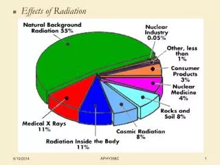
Cosmic Ray Telescope for the Effects of Radiation (CRaTER) Instrument Requirements. Justin Kasper CRaTER Instrument Scientist MIT & Boston University. CRaTER Organization Chart. Theory of Operation. Pairs of thin and thick Silicon detectors. A-150 Human tissue equivalent plastic (TEP).

E N D
Cosmic Ray Telescope for the Effects of Radiation (CRaTER) Instrument Requirements Justin Kasper CRaTER Instrument Scientist MIT & Boston University
Theory of Operation Pairs of thin and thick Silicon detectors A-150 Human tissue equivalent plastic (TEP)
Moon D6 D5 A2 D4 D3 A1 D2 D1 Space Theory of Operation • Energetic charged particle enters the telescope • Particle deposits energy in components through ionizing radiation • Nuclear interactions produce energetic secondary particle • Primary and secondary particles interact with one or more detectors • Thin detectors optimized for high LET particles • Thick detectors optimized for low LET particles • Detectors with sufficient energy deposition cross trigger threshold • Digital logic compares coincidence with event mask of desirable events • Pulse height analysis (PHA) is conducted on every detector to measure energy deposition
Heritage • CRaTER is not directly derived from an existing instrument. • The three teams (BU, MIT, Aerospace) with engineering tasks have all produced particle instruments for spaceflight. • The company providing the silicon semiconductors (Micron Semiconductor) has produced detectors for many successful flights. The particular detectors we are purchasing for the engineering model (and likely for the flight model) use dies developed for a previous mission. • Tissue equivalent plastic (TEP) has been flown in space, including investigations on the space station.
CRaTER Instrument Requirement Documents • Level 1 Documents • LRO Program Requirements Document, ESMD-RLEP-0010 • Level 2 Documents • CRaTER Instrument Requirements Document, 32-01205 01 • CRaTER Data Management Plan • LRO Mission Requirements Document, 431-RQMT-000004 • LRO Mission Concept of Operations, 431-OPS-000042 • LRO Technical Resource Allocations, 431-RQMT-000112 • LRO Pointing and Alignment Specification, 431-SPEC-000113 • LRO Electrical Systems Specification, 431-SPEC-000008 • LRO Mechanical Systems Specification, 431-SPEC-000012 • LRO Thermal Systems Specification, 431-SPEC-000091 • LRO Mission Assurance Requirements, 431-RQMT-000174 • LRO Contamination Control Plan, 431-PLAN-000110 • LRO Data Management Plan, 431-PLAN-000182 • Level 3 • Instrument Payload Assurance Implementation Plan, 32-01204 • LRO to CRaTER Mechanical Interface Document, 431-ICD-000085 • LRO to CRaTER Thermal Interface Control Document, 431-ICD-000118 • LRO to CRaTER Electrical Interface Control Document, 431-ICD-000094 • LRO to CRaTER Data Interface Control Document, 431-ICD-000104 • LRO Ground Systems ICD, 431-ICD-000049 (MOC to SOC)
CRaTER Science Operations Center Driving Level 3 Requirements
Instrument Block Diagram MIT Aerospace
Instrument Verification • The CRaTER Performance and Environmental Verification Plan (32-01206) describes the plan to verify the CRaTER requirements in accordance with the CRaTER Calibration Plan (32-01207), CRaTER Contamination Control Plan (32-01203), and the CRaTER Performance Assurance Implementation Plan (32-01204) • The verification program is designed to provide the verifications listed below: • The instrument meets its functional and design requirements. • Fabrication defects; marginal parts, and marginal components (if any exist) are detected early in the test sequence. • The instrument can survive and perform as required in the environments predicted to be encountered during transportation, handling, installation, launch, and operation. • The instrument has met its qualification and acceptance requirements. • The most significant verification testing beyond the standard set of environmental tests is a series of runs in particle accelerators to verify the performance of the detectors and the evolution of the LET spectrum after propagation through the TEP • Reporting • If a test or analysis cannot be satisfactorily completed, then a malfunction report will be produced by the test conductor. It will provide all the particular information detailing the malfunction. A malfunction may result in premature test termination, depending on operation procedures. Regardless of this, a malfunction report will be filed with the Verification Report for the activity. • Detailed test procedures and specifications will be written, reviewed, and approved by the CRaTER Project, prior to instrument-level verification testing. The lead individual for each procedure depends upon the category:Environmental Requirements (Project Engineer); Performance Requirements (Project Scientist); Contamination Requirements (Contamination Engineer); Interface Requirements (Cognizant Design Engineer); Calibration Requirements (Project Scientist)
Instrument Current Status • Major trade studies since Instrument inception which have been closed • We have decided to use two pieces of TEP with different lengths instead of the three TEP sections in the original proposal • We have increased the thickness of the shielding to raise the minimum energy up to 17 MeV for protons from the several MeV limit in the proposal • We have increased the total number of detectors from 5 to 6 • The detectors now come in pairs of thin and thick detectors to span the expected range of LET • We varied the diameter of the detectors and the height of the telescope to optimize the geometrical factor, the fields of view, and the uncertainty in pathlength • Major ongoing trade studies which could impact either Instrument top-level requirements or the interface to the Spacecraft • None • Analyses currently being performed • Thermal model of the instrument supplied to Goddard, spacecraft model supplied by Goddard and integrated. Simulations are time-dependent and have been run over multiple lunar orbits understand thermal variations • Numerical simulations of radiation transport through the current telescope design to study the expected range of LET measurements • Mechanical model • Hardware currently in development (breadboards, prototypes) • Designing and procuring parts for our engineering model • Eight detectors for the engineering model have been ordered
Summary • We have documented the flow of requirements from project to subassembly • overall LRO Level 1 requirements down to CRaTER measurements • CRaTER Level 2 instrument requirements • CRaTER Level 3 subassembly requirements • Telescope • Electronics • Constraints on LRO have been flowed down and captured in the MRD. • We have shown that the CRaTER design can meet the data products we are responsive to • Detectors for the engineering model have been ordered and beam tests are being planned • Heritage technology demonstrates that CRaTER design is realizable • The CRaTER team is ready to proceed with preliminary design