Download
1 / 26
260 likes | 264 Views
Use stacks and queues to extract and count regions in an input image. Assign a distinct gray-level value to each region for visualization purposes. Output a labeled image and the number of regions.

E N D
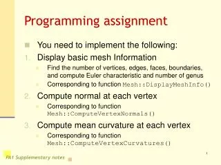
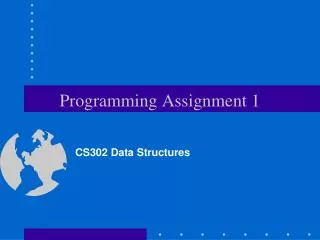
Programming Assignment 2 CS 302 Data Structures Dr. George Bebis
Objective: Use Stacks and Queues to Count and Label Regions input image 1. Extract regions and count them 2. Assign a distinct gray-level value to each region (i.e., for visualization purposes) output image Output (1) labeled image (2) number of regions
Project Goals • Improve your skills with manipulating stacksand queues (use array-based stacks/queues). • Illustrate how to convert a recursive algorithm to an iterativeone. • Learn more about image processing.
Application: automatically count and label galaxies in images captured by NASA’s Hubble telescope NASA’s Hubble Telescope Webpage http://hubble.nasa.gov/
Input Image Thresholding Remove Small Holes & Smooth Boundaries Count Regions Display labeled image & report number of regions Labeling and counting regions (1) Add a new option to the driver called “Count/Label Regions” (2) The steps shown in the diagram should be executed when the user selects this option.
Thresholding • Separate most important galaxies from background. • Precursor step to any high-level image analysis system.
threshold(T) – member function • Each pixel in the input image is compared against a threshold. • Values greater than the threshold are set to 255, while values less than the threshold are set to 0.
Results using different thresholds original threshold=128 threshold=10 threshold=230
Input Image Thresholding Remove Small Holes & Smooth Boundaries Count Regions Display labeled image & report number of regions Labeling and counting regions
Remove Small Holes and Smooth Boundaries • Typically, further processing is required to improve the results of thresholding: • Some regions in the thresholded image might contain small holes • Boundaries might be too noisy • We will use dilation/erosion to remove small holes.
dilate() – member function at least one neighbor is 255 otherwise
dilate() - example • Dilation “expands” the size of a region • Adds a layer of boundary pixels original thresholded dilated
erode() – member function at least one neighbor is 0 otherwise
erode() - example • Erosion “shrinks” the regions (i.e., removes a layer of boundary pixels) original thresholded eroded
Removing holes and smoothing boundaries • Threshold, then apply dilation to fill in the holes. • Apply erosion on the dilated image to restore the size of the regions. threshold original dilate results of dilation followed by erosion erode
Input Image Thresholding Remove Small Holes & Smooth Boundaries Count Regions Display labeled image & report number of regions Labeling and counting regions: flowchart
Connected Components Algorithm • Finds the connected components in an image • Assigns a unique label to all the pixels in the same component.
Connected Components 1. Scan the thresholded image to find an unlabeled white (255) pixel and assign it a new label L. 2. Recursively assign the label L to all of its white neighbors. 3. Stop if there are no more unlabeled white pixels. 4. Go to step 1 thresholded image (i.e., after dilation/erosion) output (i.e., labeled) image 1st 2nd
int computeComponents(inputImage, outputImage) (client function) initialize outputImage --> 255 (white) connComp=0; for (i=0; i<N; i++) for(j=0; j<M; j++) if(inputImage[i][j] == 255 && outputImage[i][j]==255) { ++connComp; label = connComp * 10; // label findComponent // recursively // or iteratively – user specified findComponentBFS(inputImage, outputImage, i, j, label); findComponentDFS(inputImage, outputImage, i, j, label); } return connComp; Extra credit if you implement the recursive version too.
Breadth-First-Search (BFS) - Queues • The main structure used used by BFS is the queue. • BFS uses a queue to “remember” the neighbors of pixel (i,j) that need to be labeled in future iterations. • The closest neighbors of (i,j) are labeled first. • BFS will first label all pixels at distance 1 from (i,j), then at distance 2, 3, etc.
findComponentBFS(inputImage, outputImage, i, j, label) (client function) Queue.MakeEmpty(); Queue.Enqueue((i,j)); // initialize queue while(!Queue.IsEmpty()) { Queue.Dequeue((pi,pj)); outputImage[pi][pj] = label; // label this pixel for each neighbor (ni,nj) of (pi,pj) // push neighbors if(inputImage[ni][nj] == 255 && outputImage[ni][nj] == 255) { Queue.Enqueue((ni,nj)); outputImage[ni][nj] = -1; // mark this pixel to avoid duplicates } } Extra credit if the queue is templated!
1 1 P10 255 1 1 1 1 dequeue dequeue p2 p10 p3 p4 p10 p3 p4 P1 dequeue dequeue dequeue continue .. p3 p4 p4 p5 p5
Depth-First-Search (DFS) - Stacks • The main structure used used by DFS is the stack. • DFS uses a stack to “remember” the neighbors of pixel (i,j) that need to be labeled in future iterations. • The most recently visited pixels are visited first (i.e., not the closest neighbors) • DFS follows a path as deep as possible in the image. • When a path ends, DFS backtracks to the most recently visited pixel.
findComponentDFS(inputImage, outputImage, i, j, label) (client function) Stack.MakeEmpty(); Stack.Push((i,j)); // initialize stack while(!Stack.IsEmpty()) { Stack.Pop((pi,pj)); outputImage[pi][pj] = label ; // label this pixel for each neighbor (ni,nj) of (pi,pj) // push neighbors if(inputImage[ni][nj] == 255 && outputImage[ni][nj] == 255) { Stack.Push((ni,nj)); outputImage[ni][nj] = -1; // mark this pixel to avoid duplicates } } Extra credit if the stack is templated!
1 1 P10 255 1 1 1 1 1 pop pop pop pop pop pop etc. P4 P5 P6 P7 P3 P3 P3 P3 P3 P10 P10 P10 P10 P10 P1 P2 P2 P2 P2 P2