Download
1 / 36
360 likes | 389 Views
Explore four alternatives to mitigate branch hazards in pipelines, including Delayed Branch implementation, slot scheduling strategies, and canceling branches to boost performance and reduce penalties. Evaluate performance impact with branch alternatives.

E N D
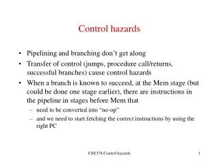
Four Branch Hazard Alternatives #1: Stall until branch direction is clear #2: Predict Branch Not Taken • Execute successor instructions in sequence • “Squash” instructions in pipeline if branch actually taken • Advantage of late pipeline state update • 47% MIPS branches not taken on average • PC+4 already calculated, so use it to get next instruction #3: Predict Branch Taken • 53% MIPS branches taken on average • But haven’t calculated branch target address in MIPS • MIPS still incurs 1 cycle branch penalty • Other machines: branch target known before outcome
Four Branch Hazard Alternatives #4: Delayed Branch (Compiler help) • Define branch to take place AFTER a following instruction branch instruction sequential successor1 sequential successor2 ........ sequential successorn branch target if taken • 1 slot delay allows proper decision and branch target address in 5 stage pipeline • MIPS uses this Branch delay of length n
Reduction of Branch Penalties:Delayed Branch • When delayed branch is used, the branch is delayed by n cycles, following this execution pattern: conditional branch instruction sequential successor1 sequential successor2 …….. sequential successorn branch target if taken • The sequential successor instruction are said to be in the branch delay slots. These instructions are executed whether or not the branch is taken.
Reduction of Branch Penalties:Delayed Branch • In Practice, all machines that utilize delayed branching have a single instruction delay slot. • The job of the compiler is to make the successor instructions valid and useful instructions. • Fills about 60% of branch delay slots • About 80% of instructions executed in branch delay slots useful in computation • About 50% (60% x 80%) of slots usefully filled
Delayed Branch-delay Slot Scheduling Strategies The branch-delay slot instruction can be chosen from three cases: • An independent instruction from before the branch: Always improves performance when used. The branch must not depend on the rescheduled instruction. • An instruction from the target of the branch: Improves performance if the branch is taken and may require instruction duplication. This instruction must be safe to execute if the branch is not taken. • An instruction from the fall through instruction stream: Improves performance when the branch is not taken. The instruction must be safe to execute when the branch is taken.
(B) (A) (C)
Delayed Branch • Instruction in branch delay slot is always executed • Compiler (tries to) move a useful instruction into delay slot. • From before the Branch: Always helpful when possible ADD R1, R2, R3 BEQZ R2, L1 BEQZ R2, L1 DELAY SLOT ADD R1, R2, R3 - - L1: L1: • If the ADD instruction were: ADD R2, R1, R3 the move would not be possible
Delayed Branch (b) From the Target: Helps when branch is taken. May duplicate instructions ADD R2, R1, R3 ADD R2, R1, R3 BEQZ R2, L1 BEQZ R2, L2 DELAY SLOT SUB R4, R5, R6 - - L1: SUB R4, R5, R6 L1: SUB R4, R5, R6 L2: L2: Instructions between BEQ and SUB (in fall through) must not useR4.
Delayed Branch ( c ) From Fall Through: Helps when branch is not taken. ADD R2, R1, R3 ADD R2, R1, R3 BEQZ R2, L1 BEQZ R2, L1 DELAY SLOT SUB R4, R5, R6 SUB R4, R5, R6 - - L1: L1: Instructions at target (L1 and after) must not use R4 till set again. • Cancelling (Nullifying) Branch: Branch instruction indicates direction of prediction. If mispredicted the instruction in the delay slot is cancelled. Greater flexibility for compiler to schedule instructions.
Branch-delay Slot: Canceling Branches • In a canceling branch, a static compiler branch direction prediction is included with the branch-delay slot instruction. • When the branch goes as predicted, the instruction in the branch delay slot is executed normally. • When the branch does not go as predicted the instruction is turned into a no-op. • Canceling branches eliminate the conditions on instruction selection in delay instruction strategies B, C • The effectiveness of this method depends on whether we predict the branch correctly. • In practice 50% of time, we have no stalls (nop).
Performance of Branch Schemes • The effective pipeline speedup with branch penalties: (assuming an ideal pipeline CPI of 1) Pipeline speedup = Pipeline depth 1 + Pipeline stall cycles from branches Pipeline stall cycles from branches = Branch frequency X branch penalty Pipeline speedup = Pipeline Depth 1 + Branch frequency X Branch penalty
Evaluating Branch Alternatives Scheduling Branch CPI speedup v. scheme penalty unpipelined Stall pipeline 1 1.14 4.4 Predict taken 1 1.14 4.4 Predict not taken 1 1.09 4.5 Delayed branch 0.5 1.07 4.6 Conditional & Unconditional = 14%, 65% change PC (taken)
Delayed Branch • Limitations of delayed branch • Compiler may not find appropriate instructions to fill delay slots. Then it fills delay slots with no-ops. • Visible architectural feature – likely to change with new implementations • Pipeline structure is exposed to compiler. Need to know how many delay slots.
Delayed Branch • Compiler effectiveness for single branch delay slot: • Fills about 60% of branch delay slots • About 80% of instructions executed in branch delay slots useful in computation • About 50% (60% x 80%) of slots usefully filled • Delayed Branch downside: As processor go to deeper pipelines and multiple issue, the branch delay grows and need more than one delay slot • Delayed branching has lost popularity compared to more expensive but more flexible dynamic approaches • Growth in available transistors has made dynamic approaches relatively cheaper
Dynamic Branch Prediction • Builds on the premise that history matters • Observe the behavior of branches in previous instances and try to predict future branch behavior • Try to predict the outcome of a branch early on in order to avoid stalls • Branch prediction is critical for multiple issue processors • In an n-issue processor, branches will come n times faster than a single issue processor
T NT NT State 1 Predict Taken State 0 Predict Not Taken T Basic Branch Predictor • Use a 1-bit branch predictor buffer or branch history table • 1 bit of memory stating whether the branch was recently taken or not • Bit entry updated each time the branch instruction is executed
1-bit Branch Prediction Buffer • Problem – even simplest branches are mispredicted twice LD R1, #5 Loop: LD R2, 0(R5) ADD R2, R2, R4 STORE R2, 0(R5) ADD R5, R5, #4 SUB R1, R1, #1 BNEZ R1, Loop First time: prediction = 0 but the branch is taken change prediction to 1 miss Time 2, 3, 4: prediction = 1 and the branch is taken Time 5: prediction = 1 but the branch is not taken change prediction to 0 miss
Superpipelining: MIPS R4000 Integer pipeline • 8 Stage Pipeline: • IF–first half of fetching of instruction; PC selection happens here as well as initiation of instruction cache access. • IS–second half of access to instruction cache. • RF–instruction decode and register fetch, hazard checking and also instruction cache hit detection.
Superpipelining: MIPS R4000 Integer pipeline • 8 Stage Pipeline: • EX–execution, which includes effective address calculation, ALU operation, and branch target computation and condition evaluation. • DF–data fetch, first half of access to data cache. • DS–second half of access to data cache. • TC–tag check, determine whether the data cache access hit. • WB–write back for loads and register-register operations. • 8 Stages: How many stalls occur due to load dependencies and control hazards?
Stalls in MIPS R4000 IF IS IF RF IS IF EX RF IS IF DF EX RF IS IF DS DF EX RF IS IF TC DS DF EX RF IS IF WB TC DS DF EX RF IS IF TWO Cycle Load Latency IF IS IF RF IS IF EX RF IS IF DF EX RF IS IF DS DF EX RF IS IF TC DS DF EX RF IS IF WB TC DS DF EX RF IS IF THREE Cycle Branch Latency (conditions evaluated during EX phase) Delay slot plus two stalls Branch likely cancels delay slot if not taken
Floating Point/Multicycle Pipelining in MIPS • Completion of MIPS EX stage floating point arithmetic operations in one or two cycles is impractical since it requires: • A much longer CPU clock cycle, and/or • An enormous amount of logic. • Instead, the floating-point pipeline will allow for a longer latency. • Floating-point operations have the same pipeline stages as the integer instructions with the following differences: • The EX cycle may be repeated as many times as needed. • There may be multiple floating-point functional units. • A stall will occur if the instruction to be issued either causes a structural hazard for the functional unit or cause a data hazard.
Floating Point/Multicycle Pipelining in MIPS • The latency of functional units is defined as the number of intervening cycles between an instruction producing the result and the instruction that uses the result (usually equals stall cycles with forwarding used). • The initiation or repeat interval is the number of cycles that must elapse between issuing an instruction of a given type.
Extending The MIPS Pipeline to Handle Floating-Point Operations: Adding Non-Pipelined Floating Point Units (In Appendix A)
Extending The MIPS Pipeline: Multiple Outstanding Floating Point Operations Latency = 0 Initiation Interval = 1 Latency = 6 Initiation Interval = 1 Pipelined Integer Unit Hazards: RAW, WAW possible WAR Not Possible Structural: Possible Control: Possible Floating Point (FP)/Integer Multiply EX IF ID WB MEM FP Adder FP/Integer Divider Latency = 3 Initiation Interval = 1 Pipelined Latency = 24 Initiation Interval = 25 Non-pipelined
Latencies and Initiation Intervals For Functional Units Functional Unit Latency Initiation Interval Integer ALU 0 1 Data Memory 1 1 (Integer and FP Loads) FP add 3 1 FP multiply 6 1 (also integer multiply) FP divide 24 25 (also integer divide) Latency usually equals stall cycles when full forwarding is used
Pipeline Characteristics With FP • Instructions are still processed in-order in IF, ID, EX at the rate of instruction per cycle. • Longer RAW hazard stalls likely due to long FP latencies. • Structural hazards possible due to varying instruction times and FP latencies: • FP unit may not be available; divide in this case. • MEM, WB reached by several instructions simultaneously. • WAW hazards can occur since it is possible for instructions to reach WB out-of-order. • WAR hazards impossible, since register reads occur in-order in ID. • Instructions are allowed to complete out-of-order requiring special measures to enforce precise exceptions.
IF ID M1 M2 M3 M4 M5 M6 M7 WB MUL.D MEM CC 10 CC 1 CC 2 CC 3 CC 4 CC 5 CC 6 CC 7 CC 8 CC 9 CC 11 ADD.D IF ID A1 A2 A3 A4 WB MEM L.D EX WB IF ID MEM IF ID EX WB S.D MEM FP Operations Pipeline Timing Example All above instructions are assumed independent
CC 10 CC 1 CC 2 CC 3 CC 4 CC 5 CC 6 CC 7 CC 8 CC 9 CC 11 CC12 CC13 CC14 CC15 CC16 CC17 CC18 IF ID M1 M2 M3 M4 M5 M6 M7 WB MEM IF ID A1 A2 A3 A4 WB MEM IF ID EX WB MEM IF ID EX WB MEM STALL STALL STALL STALL STALL STALL STALL STALL STALL STALL STALL STALL STALL STALL STALL STALL STALL FP Code RAW Hazard Stalls Example(with full data forwarding in place) L.D F4, 0(R2) MUL.D F0, F4, F6 ADD.D F2, F0, F8 S.D F2, 0(R2) Third stall due to structural hazard in MEM stage 6 stall cycles which equals latency of FP add functional unit
Dealing with RAW • Longer latency pipes cause the frequency of RAW stalls to go up. • More complicated forwarding • Frequent compiler scheduling • More advanced techniques to be covered later
IF ID M1 M2 M3 M4 M5 M6 M7 WB MEM CC 10 CC 1 CC 2 CC 3 CC 4 CC 5 CC 6 CC 7 CC 8 CC 9 CC 11 IF ID A1 A2 A3 A4 WB MEM EX EX WB WB IF IF ID ID MEM MEM IF IF IF ID ID ID EX EX EX WB WB WB MEM MEM MEM FP Code Structural Hazards Example MULTD F0, F4, F6 . . . (integer) . . . (integer) ADDD F2, F4, F6 . . . (integer) . . . (integer) LD F2, 0(R2)
Dealing with Structural Hazards • Option 1: Track the use of the write port; stall instruction in ID if there is a collision. • Maintain the property of stalling instruction only in ID. • Extra HW (e.g., write conflict logic). • Option 2: Stall a conflict instruction at MEM entry. • Flexible in choose a instruction to be stalled (give priority to the longest latency). • Complicates pipeline control.
Dealing with WAW Hazards • Option 1: Delay LD until ADDD enter MEM • Option 2: Stamp out the result of ADDD. WAW Hazards