Download
1 / 21
210 likes | 460 Views
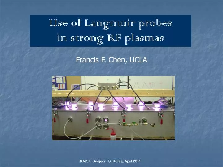
Use of Langmuir probes in strong RF plasmas. Francis F. Chen, UCLA. KAIST, Daejeon, S. Korea, April 2011. Commercial probe systems. Shown here is the Hiden ESPION probe. I use the older Hiden ESP probe software, but I make my own probes.

E N D
Use of Langmuir probes in strong RF plasmas Francis F. Chen, UCLA KAIST, Daejeon, S. Korea, April 2011
Commercial probe systems Shown here is the Hiden ESPION probe. I use the older Hiden ESP probe software, but I make my own probes. I presume you are familiar with the PlasMart probe.
The Chen B probe To reject RF pickup, resonant chokes (inductors) and a good auxiliary electrode are needed.
The choke must be >200 kW This is a good choke. High Z is good for low density. High frequency can use lower Z. It is sometimes possible to adjust the RF frequency to match the choke.
How RF distorts the I-V characteristic The RF shifts Vp back and forth. Since the I-V curve is nonlinear, the average current does not reproduce the curve. This shows what the uncompensated I-V curve would look as the RF pickup voltage is varied.
Why the auxiliary electrode is needed Probe tip Cs1 causes the choke to lose part of the oscillation of the probe. The large,floating auxiliary electrode (Zx) strongly drives the choke to oscillate with the plasma’s RF fluctuations.
The orbital-motion-limited theory Large probe, dense plasma, thin sheath Small probe, weak plasma, thick sheath Langmuir’s Orbital-Motion-Limited (OML) theory
Langmuir’s simple OML formula OML is valid only when the sheath is so thick that there is no “absorption radius”. However, it works better than other theories even when it should not be applicable. Both Hiden and PlasmArt use this simple formula. To use this formula, probe tips should be as thin as possible to minimize Rp/lD.
The simple OML formula Ap is the probe tip area, Mi the ion mass, and Vp the probe potential relative to the plasma potential. The ion saturation current Isat is independent of Te and can be used easily to measure density n. Isat varies as the square root of Vp. This is a characteristic of ion orbiting when there is no absorption radius. However, the linear I2 – Vp relation is followed even when the Rp/lD is not so large!
How did Langmuir get such a simple formula? This is what he started with for Maxwellian ions: . s is an assumed sheath radius at which ions start with their thermal velocities
Then he made some dubious approximations The ion temperature cancels out!
Attempt to use the exact OML formula At high density, the curve does not fit a straight line. Using the exact OML formula gives too much curvature even if the sheath radius is adjusted to give the best fit. It is still unknown why the I2-V curve is so close to linear.
The semilog electron curve 1 First, we have to fit the ions so that we can subtract them
The semilog electron curve 2 Now we make the semilog electron curve Note that the right amount of ion current added back is essential
Apparatus for helicon thruster 1 magnet, 65 gauss 2 magnets, 280 gauss max (lower)
Effect of auxiliary electrode 1: no electrode Te = 3.65 eV N = 15.8E11 Te = 10.4 eV The I-V curve looks more rounded. The I2-V curve is linear, but goes down fast.
Effect of auxiliary electrode 2: with electrode Te = 3.01 eV The temperature is more normal, but the high-Te part still exists. Need a larger auxiliary electrode. n = 16.8E11 I-V curve more normal.
1000 W with a 5-mil probe The thinnest probe (125 mm diam) gives I2-V curves that bend at high density. There is no theory that predicts the curve shape. This probe will glow in the discharge unless the sweep time is minimized. We can use a thick probe and thin-sheath theory, but the discharge will be disturbed by the probe current.