Download
1 / 21
220 likes | 516 Views
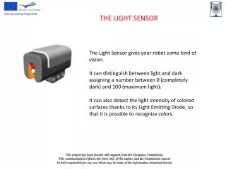
NaPiCa Light Sensor. Oct 2009. NaPiCa Light Sensor. SMD. Description NaPiCa is a visible light sensor (photo IC). Design consists of a photodiode and a built-in current amplifier. Function

E N D
NaPiCa Light Sensor Oct 2009
NaPiCa Light Sensor SMD Description NaPiCa is a visible light sensor (photo IC). Design consists of a photodiode and a built-in current amplifier. Function NaPiCa sensor works by detecting visible light and converting it to electrical current. A special filter allows sensitivity that resembles the human eye. Usage Visible light sensors are used to conserve energy, reduce environmental impact, improve safety and convenience. Through-hole Chip
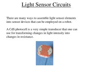
Material Product Name Photodiode Phototransistor Silicon Visible Light Sensor NaPiCa Silicon Photo IC Solar cell Amorphous silicon Cadmium sulfide CdS photoconductive cell Photodiode Output current is low and requires an amplifier for high output current. Phototransistor Integrated photodiode combined with a transistor. Good performance with low output current. Silicon Photo IC Integrated photodiode and amplifier IC with a high photocurrent output. Amorphous silicon High visual sensitivity with low photocurrent. Requires an amplifier and optical filter. Diode becomes conductive when internal resistance changes due to the illumination level. Features response similar to the human eye. Contains cadmium and not RoHS compliant. CdS photoconductive cell Technology Comparison
Wavelength Sensitivity Characteristics • Built-in optical filter provides sensitivity characteristics near human vision spectral sensitivity ⇒Peak sensitivity wavelength: 580nm (Chip design: 560nm) Infrared spectrum Visible light spectrum UV spectrum 1 0.8 Relative sensitivity Humanspectral sensitivity NaPiCa spectral sensitivity (SMD, through-hole) 0.6 0.4 NaPiCa spectral sensitivity (Chip) 0.2 0 300 400 500 600 700 800 900 1000 1100 Wavelength (nm)
10000 SMD,through-hole 1000 Photocurrent Chip 100 10 Linear output (μA) 1 Brightness(lx) 0.1 1 10 100 1000 10000 SMD / Through-hole Chip Illumination(fluorescent light) 13A 1A 5 lx 260A 20A 100 lx Linear Output Typical Characteristics Item Symbol Photocurrent 1 IL1 Photocurrent 2 IL2
No Need for External Amplifier Internal circuit Built-in amp AMS104 SMD Amp AMS402 AMS302 Chip Through-hole High sensitivity (photocurrent output)
Sensor Enclosure NaPiCa Others Incident light Incident light Cover Cover Incident light attenuation Incident light attenuation High sensitivity Low sensitivity Insufficient output Sufficient output
Temperature Stability NaPiCa Others Approx. -50% to +100% Approx. 5% Sensitivity Sensitivity -30℃ +85℃ -30℃ +85℃ Temperature Temperature
Terminal Shape NaPiCa SMD Close-up of terminal soldering inspection
0.55 1.0 1.25 2.0 2.0 3.2 Chip Version AMS104 AMS402 Compact,small currentconsumption ※ Built-in amp circuit ※ Built-in amp circuit Photocurrent = 260μA @100 lx Photocurrent = 20μA @100 lx (Dimension unit: mm)
Brightness vs. Output Voltage Vcc Light source: fluorescent, power voltage: 5V, ambient temperature: 25oC Light AMS104 Load resistance RL Vo IL RL
Apply voltage to photodiode Forward voltage Reverse voltage + + + × - - - YES NO Input side (cathode) Light uA Amp pA Output side (anode) Figure 1 – Reverse voltage applied to photodiode Reverse Voltage & Photocurrent
Dark Current (Leakage Voltage) When reverse voltage is applied into a sensor at a dark place, leakage voltage occurs. This value is called “dark state current”. Sensors have leakage current because of semiconductor characteristics. Maximum 0.3μA (SMD, through-hole), maximum 0.05μA (Chip)
Linear output 100 lx:260A Cathode 5 lx:13A Anode Photocurrent Reverse voltage Vcc Power voltage Microcomputer Load resistance Output voltage Comparator Light Sensor Reference Data Figure 2 – Photocurrent vs. brightness characteristics Figure 3 –General circuit configuration
Dark current (uA) Power dissipation (mW) Ambient temp. (°C) Ambient temp. (°C) Photocurrent (uA) Brightness (lx) Power Dissipation, Dark Current, Photocurrent Figure 4 – Power dissipation vs. ambient temperature characteristics Figure 5 – Dark current vs. ambient temperature characteristics Light source: fluorescent, CEI standard A light source; Reverse voltage: 5V; Ambient temp.: 25oC Figure 6 – Photocurrent vs. brightness characteristics
Relative photocurrent (uA) Ambient temp. (°C) Relative photocurrent (uA) Ambient temp. (°C) Switching time (ms) Load resistance (kΩ) Relative Current, Switching Time Light source: fluorescent; Brightness: 100 lx; Reverse voltage: 5 V Figure 7 – Relative photocurrent vs. ambient temp. characteristics Light source: fluorescent lamp; Brightness: 100 lx; Ambient temp: 25oC Light source: White LED; Reverse voltage: 2.5 V; Load resistance power: 2.5 V; Ambient temp.: 25oC Figure 8 – Relative photocurrent vs. reverse voltage characteristics Figure 9 – Switching time vs. load resistance characteristics NaPiCa SMD
NaPiCa Product Line AMS302 Through-hole AMS104 SMD • CdS replacement • 260μA photo current • Compact design • Low current consumption AMS402 Chip • Automatic mounting • 260μA photo current
Display Backlight Control NaPiCa light sensor Vcc Light ③ Microcomputer adjusts the brightness of LCD backlight Photo-current ① Photocurrent of light sensors varies depending on ambient temperature Amp Driver μP R Load ② Change of load resistance voltage
NaPiCa Advantage • Built-in amplifier eliminates external amplification • Photo IC with high sensitivity • Temperature stability with minimum sensitivity effect • RoHS friendly silicon design and easy CdS cell replacement • SMD, through-hole and chip design