Download
1 / 12
120 likes | 180 Views
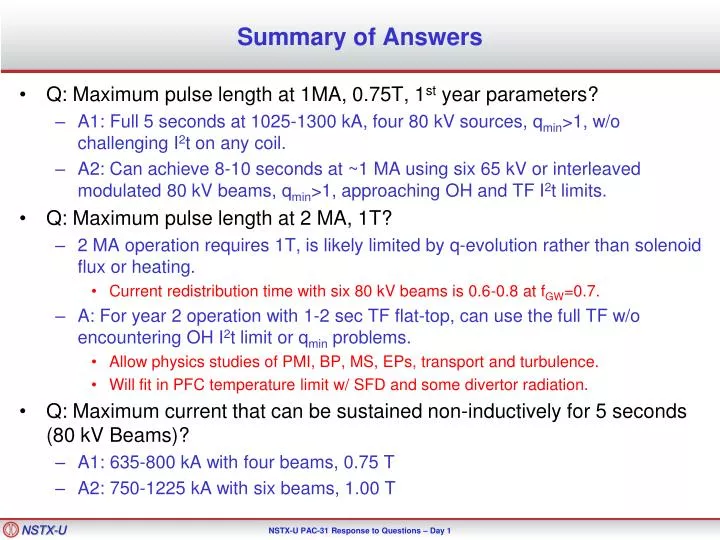
Summary of Answers. Q: Maximum pulse length at 1MA, 0.75T, 1 st year parameters? A1: Full 5 seconds at 1025-1300 kA, four 80 kV sources, q min >1, w/o challenging I 2 t on any coil.

E N D
Summary of Answers • Q: Maximum pulse length at 1MA, 0.75T, 1st year parameters? • A1: Full 5 seconds at 1025-1300 kA, four 80 kV sources, qmin>1, w/o challenging I2t on any coil. • A2: Can achieve 8-10 seconds at ~1 MA using six 65 kV or interleaved modulated 80 kV beams, qmin>1, approaching OH and TF I2t limits. • Q: Maximum pulse length at 2 MA, 1T? • 2 MA operation requires 1T, is likely limited by q-evolution rather than solenoid flux or heating. • Current redistribution time with six 80 kV beams is 0.6-0.8 at fGW=0.7. • A: For year 2 operation with 1-2 sec TF flat-top, can use the full TF w/o encountering OH I2t limit or qmin problems. • Allow physics studies of PMI, BP, MS, EPs, transport and turbulence. • Will fit in PFC temperature limit w/ SFD and some divertor radiation. • Q: Maximum current that can be sustained non-inductively for 5 seconds (80 kV Beams)? • A1: 635-800 kA with four beams, 0.75 T • A2: 750-1225 kA with six beams, 1.00 T
Background Information On Simulations (Much Covered in ASC Talk) • Typically assess a scenario using two profile and two confinement assumptions. • Good for bracketing the expected operating points. • Central NBCD tends to drive down qmin for fGW<~0.7. • The exact low-density boundary for qmin=1 depends on the configuration. • NSTX discharges become strongly susceptible to core m/n = 1/1+2/1 modes as qmin approaches 1. • Define “maximum sustainable current” as that which leads to qmin~1.1-1.2. • Typically more limiting than the solenoid flux or I2t limits. • Heating duration is a strong function of the beam voltage. • Limits are due to heating on the primary energy ion dump. • Upgraded ion dumps could result in extension of pulse lengths. • 5 seconds generally required 80 kV sources, with 1.7 MW/source
Discharges Have Shown Good Confinement and High Density and Elongation. Time Traces of Discharges with Good Confinement at High Density • Upgrade simulations generally call for H98=1 at 0.65<fGW<1.0. • Database analysis shows this regime is accessible with Upgrade-relevant shaping.
Flux Consumption Assumptions for the Upgrade Based on Extrapolation of NSTX Results • Upgrade OH capacity is substantially improved • Factor 3.5 increase in I2t limit. • Vs capability increased from 0.75 Wb to 2.1 Wb. • Very few high-performance scenarios limited by flux consumption. • Extrapolate ramp-up flux for 2MA as ~0.8 Wb. • Must keep surface voltage under (2.1-0.8)/5 = 0.25 V • 2MA scenarios project to 0.2-0.3 V. • Similar increase in TF capability. • Factor of 20 increase in I2t. • Maximum field increase by factor of ~2. • Results in quite long TF Flat-top durations compared to NSTX. • ~6.5 s at 1 T, ~11.5 s at 0.75 T
Question: Non-Inductive Sustainment Level for 5 seconds?Answer: 750-1225 kA for 1T, 635-800 kA for 0.75 T Summary of Fully Non-Inductive Scenarios at 0.75 & 1 T All the details for the 100% non-inductive scenarios bN values are similar to commonly achieved values in NSTX
Question: Pulse Duration at 1 MA?Answer #1: At 0.75 T, the Maximum Sustainable Current is in the Vicinity of 1000-1300 kA for 5 Seconds. 1100-1300 kA Scenarios Don’t Challenge OH Coil Limits Summary of 0.75 T scenarios with qmin~1.15 Sustainable current exceeds 1 MA at 0.75 T, even for most pessimistic confinement assumptions Table With Complete Details on 0.75 T Scenarios with qmin~1.15
Question: Pulse Duration at 1 MA?Answer #2: Heating and magnetic system capable of 8-10 s ~1 MA pulses! • BT=0.75 T scenarios with 5.1 or 6.6 MW input power • Interleaved 80 kV case can sustain qmin> 1with 850-1050 kA for 10 sec. • 65 kV case can sustain qmin>1 with IP=1000-1250 kA for 8 sec. NSTX Record! Example Beam Modulation Pattern Designed to Minimize qmin Variation Results in 5.1 MW for 10 s! Solenoid Current & Heating, and Plasma Current Waveforms NSTX Record!
Question: Pulse Duration at 2 MA?Answer 1: The “maximum sustainable current” is typically a somewhat less than 2 MA. 10.2 MW, 1500-2000 kA Scenarios at fGW=1 Don’t Challenge OH Coil Limits Summary of 1.0 T scenarios with qmin~1.15 Only most optimistic projections at high fgw result in relaxed qmin>1 at 2 MA
Question: Pulse Duration at 2 MA?Answer 2: Long Current Redistribution Times Will Allow Long Pulse 2000 kA Scenarios at fGW=0.7 Only Challenge OH Coil For Unfavorable Confinement and Profiles Summary of 10.2 MW, 1.0 T , 2 MA, 5 sec. scenarios • NSTX discharges evolving to qmin<1 typically last ~4 tCR. • By similar logic, expect 2-3 seconds at 2 MA. • Sufficient for all confinement, stability, and boundary physics studies.
Divertor Temperature Can Be A Pulse Length Limiting Factor • For fexp=30 and fdiv=0.5, and no radiation: • Limited to ~1.5 second for a 1200 C divertor. • Approximately matches the expected pulse length for year 2, 1 T, 2MA operation. • Relief could come from impurity radiation. • Snowflake divertor utilized to achieve large fexp promotes detachment. • Research plan will develop radiative divertor control if SFD does not naturally develop them. • Higher density for qmin>1 purposes helps promote divertor radiation solutions. Pulse Length as a Function of Peak Heat Flux. Menard, et al., submitted to Nuclear Fusion
NSTX Context For Confinement and Flux Consumption Assumptions in Upgrade Relationship Between Confinement, Density, and Elongation Confinement Quality in Recent Lithiated Discharges Agrees Strikingly Well with ITER-98y,2 Gerhardt, et al., NF 2011 See comparison to “ST-Scaling” in talk by Y. Ren. Menard, et al., Submitted to Nuclear Fusion
Scenario Goals Can be Met over a Range of Zeff, Provided Confinement is Maintained • Li H-modes, even w/ small ELMs and controlled density, tend to have Zeff~2-4. • Best confinement at the higher Li evaporation rates. • Increasing Zeff with fixed Te reduces non-inductive fraction. • Increased Zeff, with fixed H98, results in very little change. • H98~1 confinement (or better) observed in lithiated H-modes over a range of Zeff. • The electron confinement is a critical variable in determining the scenario performance. 1.0 MA, 1.0 T, Pinj=12.6, near non-inductive 1.6 MA, 1.0 T, Pinj=10.2 MW, partial inductive 1.2 MA, 0.55 T, Pinj=8.4 MW, high bT All: fGW=0.7, H98=1