Download
1 / 51
520 likes | 679 Views
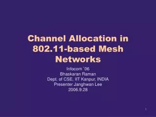
RFID Reader Networks: Channel allocation algorithms, performance evaluation and simulator. John Sum, National Chung Hsing University. OUTLINE. RFID Reader Network Reader Collision Problem Algorithms Non Progressive Progressive Hybrid Simulation Results Conclusions Simulator design.

E N D
RFID Reader Networks: Channel allocation algorithms, performance evaluation and simulator John Sum, National Chung Hsing University
OUTLINE • RFID Reader Network • Reader Collision Problem • Algorithms • Non Progressive • Progressive • Hybrid • Simulation Results • Conclusions • Simulator design RFID Reader Networks
I. RFID Reader Network RFID Reader Networks
I. RFID Reader Network • Reader Host Computer • 802.11bgn • Reader Tags • ETSI EN 302 208 (European regulation) • 15 sub-bands (channels) in the ISM band, 10 channels are available and 5 guard bands • Readers access the medium by Carrier Sense Multiple Access (CSMA) mechanism (Listen Before Talk). If the sub-band is free, the readers start to transmit into. Then, the sub-band is used for up to 4 s, after which it must be free for at least 100 ms. • EPC global Class-1 Gen-2 UHF Protocol • 50 different sub-bands. Readers randomly alternate (every 0.4 s) between bands, following the Frequency Hopping Spread Spectrum (FHSS) • Readers do not listen to the channel before accessing to it. The reader transmissions are restricted to operate in even-numbered sub-bands and tag backscatter in odd-numbered sub-bands. RFID Reader Networks
I. RFID Reader Network • Readers are powered by batteries, with much powerful computational and memory capacities. • Tags (passive) are powered by the radio signal transmitted by the readers. Memory is small. Backscattered signal is weak. RFID Reader Networks
I. RFID Reader Network RFID Reader Networks
I. RFID Reader Network RFID Reader Networks
I. RFID Reader Network • Tag collision problem • Single reader multiple tags • Multiple tags receive signal from the same reader. The backscattered signals interfere. As a result, reader could not read from anyone of them. • This problem can be alleviated by TDMA like methods. • One tag responses at a time, by something like tag address. RFID Reader Networks
I. RFID Reader Network • Reader collision problem • Multiple readers single (or multiple) tags • Neighbor readers send the same frequency signal to the air. At the same time, these two signals interfere each other. Tags are unable to backscatter signal. • This problem can be alleviated by TDMA (CSMA) or FDMA (frequency hopping) like methods. • Time slot allocation and channel allocation RFID Reader Networks
I. RFID Reader Network EPC Class 1 Gen 2 UHF Air Interface Protocol (2004) RFID Reader Networks
II. READER COLLISION PROBLEM • Operation Environment • Any two readers will have collision if their distance apart d(i,j) is within a range r and they are collecting data in the same time slot. • Readers are not able to select their frequency bands. • The readers are deployed uniformly random within an area of 100m × 100m, and are not moveable. • Each reader can only assigned with one channel τ (for i = 1, 2, · · · ,N ) in each cycle of interrogation. • No mobile reader is allowed within the area of deployment. RFID Reader Networks
II. READER COLLISION PROBLEM • Operation Mechanism • Channel allocation is done by the control computer. • Once the solution has obtained, the control computer will send message informing the readers the channels being assigned. • The readers will thus record their channels being assigned and wait for the synchronization signal from the control computer. • Once the syn. signal has been received, each reader will then operate at the dedicated channel to read the tags’ data. • Communication between the control computer and the readers are implemented by wireless LAN. RFID Reader Networks
II. READER COLLISION PROBLEM • The collision matrix: For i, j = 1, 2, • • • , N and i≠j, • The number of collision pairs (CP) in a reader network can be defined as follows: RFID Reader Networks
III. ALGORITHMS (Non Progressive) • The maximum number of channels available is predefined. • Non progressive algorithms • Heuristics • Simulated Annealing (CT, KIRK, GG) • Distributed Color Selection RFID Reader Networks
III. ALGORITHMS (Non Progressive) • Heuristics • S1 Generate random numbers in {1, 2, • • • , T} for τ1, τ2, • • • , τN as their initial random channels allocation. • S2 Random select a reader, say i. • S3 If reader’s channel assignment has no collision to its neighbor readers, then goto S2. • S4 If reader’s channel assignment has collision to its neighbors, select a new {1, 2, • • • , T} such that the number of collision pairs between the reader and its neighbors is the minimum. • S5 Repeat steps S2 to S4 until no more improvement can be made. RFID Reader Networks
III. ALGORITHMS (Non Progressive) • Simulated Annealing • S1 Generate random numbers in {1, 2, · · · , T} for τ1, τ2, · · · , τN as their initial random channels allocation. k = 0. • S2 Random select a reader, say i. Then, k = k + 1. • S3 If reader’s channel assignment has no collision to its neighbor readers, then goto S2. • S4 If reader’s channel assignment has collision to its neighbors, random generate a new {1, 2, · · · , T}. • S5 If the number of collision pairs between the reader and its neighbors reduces. RFID Reader Networks
III. ALGORITHMS (Non Progressive) • Simulated Annealing • S6 If the number of collision pairs between the reader and its neighbors increases by ∆, generate a random number u from a uniform distribution in [0, 1]. Then, • S7 Repeat steps S2 to S6 for k ≤ MaxRun. RFID Reader Networks
III. ALGORITHMS (Non Progressive) • a) Constant Temperature: For all k ≥ 0 and a << 1 is a small constant, • b) Geman-Geman Rule: For all k ≥ 0 and b is a constant, • c)Kirkpatrick et al Rule: For all k ≥ 0 and 0 < α < 1. i.e. λ(k) = αλ(k − 1). RFID Reader Networks
III. ALGORITHMS (Progressive) • The maximum number of channels required for allocation is determined automatically by the algorithms. • Progressive algorithms • Progressive Heuristics • Progressive SA (CT, KIRK, GG) • Colorwave RFID Reader Networks
III. ALGORITHMS (Progressive) RFID Reader Networks
IV. SIMULATION RESULTS RFID Reader Networks
IV. SIMULATION RESULTS • 250 readers in random locations within an area of 100m×100m. • Readers at the end of an edge are neighbors. • The number of edges in the experimental network is 3830. • In average, each reader has 15.32 neighbors. • The constants a, d, c, and α in the simulated annealing algorithms are 0.01, 1, 2 and 0.99 respectively. RFID Reader Networks
IV. SIMULATION RESULTS (NP) • Comparison • Average number of collision pairs • Convergence properties • Channel distributions (Entropies) • Fault tolerance • Labels • RAND: Initial Random Allocation • HEU: Heuristic Algorithm • CT: Constant Temperature SA • GG: Geman-Geman Rule • KP: Kirkpatrick et al Rule. RFID Reader Networks
IV. SIMULATION RESULTS (NP) RFID Reader Networks
IV. SIMULATION RESULTS (NP) • Convergence – Collision Pairs VS Number of Steps RFID Reader Networks
IV. SIMULATION RESULTS (NP) Slots Distributions RFID Reader Networks
IV. SIMULATION RESULTS (P) RFID Reader Networks
IV. SIMULATION RESULTS (P) RFID Reader Networks
IV. SIMULATION RESULTS (Hybrid) RFID Reader Networks
IV. SIMULATION RESULTS(Fault tolerance) • Experimental setup • 20 random reader networks are generated • Channel allocation for each of these reader networks is done by the 5 algorithms (heuristics, SA-CT, SA-GG, SA-KP, and Colorwave) separately. • For heuristics, SA-CT, SA-GG, SA-KP algorithms, the number of available channels is fixed to 16. • For Colorwave, the initial channel number is set to 16. • Once the channel allocations have been finished, all readers are set randomly to fault with fault rate 0.05. This step is repeated 20 times. RFID Reader Networks
IV. SIMULATION RESULTS RFID Reader Networks
IV. SIMULATION RESULTS Colorwave algorithm RFID Reader Networks
V. CONCLUSIONS • Towards a framework for the RFID developer to investigate the performance of an RFID system • Simulate the environment in which the RFID readers are not perfect. • Algorithms for solving RCP are introduced, including • HEUR, SA-CT, SA-KIRK, SA-GEM, DCS • P-HEUR, PSA-CT, PSA-KIRK, PSA-GEM, CW • HYBRID RFID Reader Networks
V. CONCLUSIONS • Computational Speed (for NP type): • HEUR > DCS > SA • Channel Distribution (for NP type): • SA > DCS > HEUR • DCS is unable to solve the problem RFID Reader Networks
V. CONCLUSIONS • Channel Distribution (Progressive) • PSA > P.HEUR > CW • Fault tolerance • Similar behaviors • Overall (Comp. Speed + Distribution) • HYBRID > Progressive > Non-Progressive RFID Reader Networks
V. CONCLUSIONS • Even slot distributions Demand on high bandwidth communication between readers and control computer can be reduced. RFID Reader Networks
VI. Simulator System Design 管理系統與RFID網路架構 RFID Reader Networks
VI. Simulator System Design 管理系統程式設計 RFID Reader Networks
VI. Simulator System Design 模擬器程式設計 RFID Reader Networks
VI. Simulator System Design • MATLAB M-file, MATLAB FIG-file。 • User is able to set the following parameters for simulation • Number of Readers • Transmission Range • Number of Channel • Number of Steps • Reader Fault Rate • Channel Allocation Algorithm RFID Reader Networks
VI. Simulator System Design RFID Reader Networks
VI. Simulator System Design • 250個讀取器隨機部署在100m×100m內 • 讀取器故障率為0.05 • 通道配置之方法為啟發式演算法 • 紅色的方框代表讀取器為故障 即時監控故障讀取器 RFID Reader Networks
VII What’s Next RFID Reader Networks
VII What’s Next RFID Reader Networks
VII What’s Next RFID Reader Networks
VII What’s Next RFID Reader Networks
VII What’s Next Hai Liu, Miodrag Bolic, Amiya Nayak and Ivan Stojmenovi, Integration of RFID and wireless sensor networks, Encyclopedia on Ad Hoc and Ubiquitous Computing, Dharma P. Agrawal, Bin Xie (eds.), World Scientific Press, Singapore, 2009. RFID Reader Networks
VII What’s Next • Cyber-digital Ecosystem: Systems merge. • Telecom networks • Connecting people • Each person is identified by a mobile phone number (or multiple phone numbers) • Facebook • Connecting people • Each person is identified by an account name (or multiple account names) • Internet • Connecting networks • Each network is uniquely identified by a domain ID • Computer network • Connecting computing machines • Each machine is uniquely identified by a unique local IP address RFID Reader Networks
VII What’s Next • Cyber-digital Ecosystem: Systems merge. • Sensor networks • Connecting sensors for environmental information • Each information is uniquely identified by a unique sensor ID • RFID systems • Connecting physical stuffs • Each stuff is uniquely identified by a tag ID • Vehicle networks • Connecting Moving compartments • Each compartment is a LAN which is identified by an ID • Personal area networks • Connecting body sensors, wireless headset • Each device is uniquely identified by a unique ID • Finally …… RFID Reader Networks
VII What’s Next RFID Reader Networks