Download
1 / 6
70 likes | 293 Views
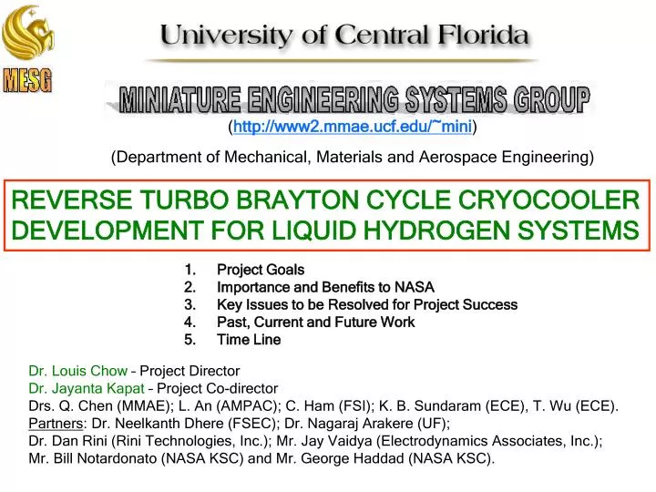
( http://www2.mmae.ucf.edu/~mini ) (Department of Mechanical, Materials and Aerospace Engineering). REVERSE TURBO BRAYTON CYCLE CRYOCOOLER DEVELOPMENT FOR LIQUID HYDROGEN SYSTEMS. Project Goals Importance and Benefits to NASA Key Issues to be Resolved for Project Success

E N D
(http://www2.mmae.ucf.edu/~mini) (Department of Mechanical, Materials and Aerospace Engineering) REVERSE TURBO BRAYTON CYCLE CRYOCOOLER DEVELOPMENT FOR LIQUID HYDROGEN SYSTEMS • Project Goals • Importance and Benefits to NASA • Key Issues to be Resolved for Project Success • Past, Current and Future Work • Time Line Dr. Louis Chow – Project Director Dr. Jayanta Kapat – Project Co-director Drs. Q. Chen (MMAE); L. An (AMPAC); C. Ham (FSI); K. B. Sundaram (ECE), T. Wu (ECE). Partners: Dr. Neelkanth Dhere (FSEC); Dr. Nagaraj Arakere (UF); Dr. Dan Rini (Rini Technologies, Inc.); Mr. Jay Vaidya (Electrodynamics Associates, Inc.); Mr. Bill Notardonato (NASA KSC) and Mr. George Haddad (NASA KSC).
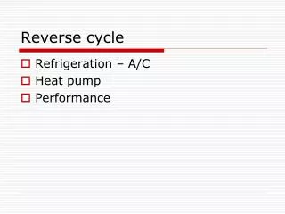
PROJECT GOAL Light in weight 20-30 W Cooling Power at 18 K TO DESIGN AND BUILD A REVERSE TURBO BRAYTON CYCLE CRYOCOOLER Affordability & Reliability High-Efficiency Compactness 55% 75% 70% 90% 85% 95% GPa
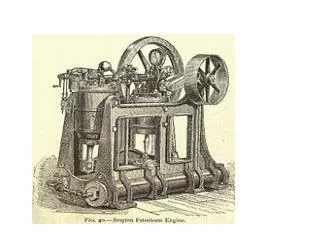
IMPORTANCE & BENEFITS TO NASA All of the previous attempts of flight cryocoolers have cooling capacities less than 2 W at liquid hydrogen temperature. There are commercially available cryocoolers that have higher cooling powers but their weight restricts their possible usage for in-space applications. Long term propellant storage Cryomech G-M Cryocooler AL330 (40W @ 20K) UCF Miniature RTBC Cryocooler (20–30W @ 18K) Motor/Compressor unit 119-176 kg Motor/Compressor unit 10 kg Key Issue The rest of the cryocooler 24 kg The rest of the cryocooler 12 kg Propellant losses Ceramic micro-channel heat recuperator, Cold head, Expander/Alternator Heat regenerator, Flexible lines, Cold head Prevention 22 kg Total weight 143-200 kg Total weight Propellant management and stocking COP 0.005 COP 0.01 Solution The proposed design can significantly contribute to NASA efforts on densification and ZBO storage of cryogenic propellants for missions to Mars. Zero Boil-Off (ZBO)
KEY ISSUES March 2004 NASA Panel Advice: To reduce the scope and develop a much improved compressor/motor over the current state-of-the-art • Miniature High-speed Centrifugal Compressor Development, • High-speed, High-efficiency Motor Development, and • Integration and Testing of Compressor and Motor De-scoped from the project • The integrated compressor/motor is key to RTBC, • and is useful for many NASA and non-NASA applications. • Examples include, • Durable, light-weight cryogenic (liquid hydrogen) propellant storage and feed systems for the development of Unmanned Air Vehicles (UAV) and transport aircraft and, • Future aircraft propulsion systems driven by electric power, • where cryogenic and non-cryogenic high power density electric motors are useful. Development Of Gas Foil Bearing And Heat Recuperator
Miniature Centrifugal Compressor Design Verification by Numerical Simulation and Testing Design and Fabrication of Miniature Centrifugal Compressor • Design: • Slotless stator and high energy density permanent magnet lead to low electrical losses and high efficiency. • Cylindrical structure with a large thickness hollow shaft design optimized to provide minimal rotor imbalance and high overall structural stiffness, thereby, preventing the shaft super-critical operation. Fabrication and Integration of the 5.4 kW Motor/Two-stage Compressor Assembly 6. 5.4 kW PMSM Design CURRENT WORK FUTURE WORK PAST WORK Overall System Optimization • Design: • Rotordynamic study based on the two-impeller • mounted shaft structure using FEA 7. Two-stage Centrifugal Compressor Design Design: Completed test rig design with features like single rotor, spring loaded bearing, closed gas passage structure and precision impeller tip clearance control mechanism Some Parts Fabricated: Bearing Loader, Gas Passage, Inlet Guide Vane and Top Plate 5. Integration and Preliminary Testing of Motor/Compressor Test Assembly Design, Fabrication and Testing of High-Speed, High-Efficiency PMSM
TIME LINE • Overall Project Schedule/Tasks List • Task 1. Design and Fabrication of Miniature Centrifugal Compressor • Task 2. Design of a High-speed, High-efficiency PMSM • Task 3. Fabrication and Testing of PMSM • Task 4. Miniature Centrifugal Compressor Design Verification by Numerical Simulation and Testing • (with appropriate scaling) • Task 5. Integration and Preliminary Testing of the Motor/Compressor Assembly (by December 2005) • Task 6. 5.4 kW Permanent Magnet Synchronous Motor (PMSM) – Design (by August 2005) • Task 7. Two-stage Centrifugal Compressor – Design(by August 2005) • Task 8. Fabrication and Integration of the 5.4 kW PMSM/Two-stage Compressor Assembly • Task 9. Overall System Optimization – Systematic Testing of the Motor/Compressor Assembly, Evaluation, Possible Design Changes Overall Project Milestones: Phase III M1 – 12/31/04: Design verification of miniature centrifugal compressor by numerical simulation and testing (with appropriate scaling) (completed) M2 – 02/28/05: Design of the motor/compressor assembly test rig (completed) M3 – 07/30/05: Fabrication and integration of the motor/compressor assembly test rig (under progress) M4 – 08/31/05: Design of the 5.4 kW PMSM (under progress) M5 – 08/31/05: Design of the two-stage 313,000-rpm centrifugal helium compressor (under progress) M6 – 12/31/05: Preliminary testing of the 2 kW motor/one-stage compressor assembly