Download
1 / 17
170 likes | 312 Views
Evaluation of AoD/AoA for TGac Multi-User MIMO channel Model. Greg Breit, gbreit@qualcomm.com Hemanth Sampath, hsampath@qualcomm.com Sameer Vermani, vermani@qualcomm.com Richard Van Nee, rvannee@qualcomm.com Minho Cheong, minho@etri.re.kr Naoki Honma, honma.naoki@lab.ntt.co.jp

E N D
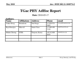
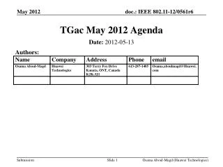
Evaluation of AoD/AoA for TGac Multi-User MIMO channel Model Greg Breit, gbreit@qualcomm.com Hemanth Sampath, hsampath@qualcomm.com Sameer Vermani, vermani@qualcomm.com Richard Van Nee, rvannee@qualcomm.com Minho Cheong, minho@etri.re.kr Naoki Honma, honma.naoki@lab.ntt.co.jp Takatori Yasushi, takatori.yasushi@lab.ntt.co.jp Yongho Seok, yhseok@lge.com Seyeong Choi, seyeong.choi@lge.com Phillipe Chambelin, philippe.chambelin@thomson.net John Benko, john.benk@orange.com Laurent Cariou, laurent.cariou@orange-ftgroup.com VK Jones, vkjones@qualcomm.com Allert Van Zelst, allert@qualcomm.com
Background • In the LA meeting, there was discussion on whether to use identical or different AoD for MU-MIMO transmission to different clients • Ref: Doc-09/0088: • Independent AoD clusters (i.e. different RTX matrices) at the AP for transmission to each client. • Ref: doc – 09/0179: • Identical AoD clusters (i.e. same RTX matrix) at the AP for transmission to each client. • Had some offline discussions on this topic with: • Vinko Erceg (Broadcom), Eldad Perahia(Intel), ETRI, Thomson, LG, NTT, Orange, Toshiba. • In this study: • We investigate the AoD/AoA diversity on MU-MIMO channel capacity • Propose a MU-MIMO channel model with minimal changes to TGn channel model.
Literature Search • J-G. Wang, A.S. Mohan, and T.A. Aubrey,” Angles-of-arrival of multipath signals in indoor environments,” in proc. IEEE Veh. Technol. Conf., 1996, pp. 155-159. • AoA measurements were made in classroom and hall scenarios. • Classroom: For the same RX location, cluster AoA from 2 different TX locations vary up to 20 degrees • Hall: For the same RX location, cluster AoA from different 2 TX locations vary up to 60 degrees. Also, clusters that are relevant for one TX location were absent for another TX location. • The above observations are applicable to the DL MU-MIMO scenario, with the following substitutions: TX STA; RX AP and AoA AoD.
AoD/AoA vs. Physical Geometry Scenario 1: Pure LOS channel • From Physics: • AP has a different AoD to STA-1 and STA-2. Also, each STA has a different AoA from AP. • The LOS steering vectors to STA-1 and STA-2 are different.
AoD/AoA vs. Physical Geometry Scenario 2: NLOS channel with scatterers far away from AP • Different scatterers may be relevant to different STAs. • AP may have a completely independent AoD for clusters corresponding to STA-1 and STA-2 • STAs may have completely independent AoA depending on location and device orientation
AoD/AoA vs. Physical Geometry Scenario 3: NLOS channel with scatterers close to AP • AP may have a similar AoDs for clusters regardless of transmission to STA-1 or STA-2. • STAs may have independent AoAs depending on location and device orientation
MU-MIMO Channel Model Proposal • Assume TGn-defined cluster AoDs and AoAs for link level simulations. • For Multi-User MIMO system simulations: • Assume TGn-defined cluster AoDs and AoAs as baseline. • For each client, a single pseudo-random offset is added to all cluster AoDs and AoAs. • Pseudo-random selection allows comparison across proposals. • Single offset retains TGn angular spacing between clusters. • NLOS Cluster AoD offsets uniformly distributed between ±30° • Based on experimental results from Wang et al. • Compromises scenarios outlined in slides 3,4,5. • NLOS Cluster AoA offsets uniformly distributed between ±180° • Clients can see independent AoA depending on orientation and location. • LOS tap AoA and AoD offsets uniformly distributed between ±180°. • Direct LOS path to each client can have independent AoA/AoD depending on location. • Pros: • Physically realistic – Introduces statistical AoA/AoD variation across clients • Minimal change to TGn channel model • Simulation complexity increase is reasonable: TX/RX correlation matrix need to be computed only once per client, for the entire simulation run.
Simulation Overview • Assumptions: • 16 TX antennas, 8 STAs, 2 RX antennas per STA • TGn channel models B, D (LOS and NLOS scenarios) used as baseline • AoD and AoA as specified in the channel model document • Composite multi-user channel matrix constructed from vertical concatenation of 8 2x16 channel matrices • Clients are effectively uncorrelated from each other • Capacity Analysis: • For each channel model, 5 cases of random per-user AoA and AoD generated • 200 channel realizations generated per case • MMSE precoder applied to each 16x16 channel instance • Post-processing SINRs calculated for each stream and subcarrier • PHY capacity for each stream/subcarrier calculated as log2(1+SINR) • For each instance, sum-average channel capacity calculated by averaging across subcarriers and summing across spatial streams • CDFs generated across all 200 channel instances
Model B Results – Capacity CDFs • Model B: 2 clusters, 0dB K factor in LOS case • Capacity CDFvaries by +20% depending on user selection and their AoA/AoD • Note #1: AoD variation in LOS channel component leads to variation of steering vectors across clients and hence improves MU-MIMO capacity.
Model D Results – Capacity CDFs • Model D: 3 clusters, 3dB K factor in LOS case • Capacity CDF varies by +/-10% depending on user selection and their AoD/AoA. • Note #1: Artifact of TGn model: TGn AoA specification result in optimal per-user MIMO capacity. Any AoA offset tends to degrade per-user MIMO capacity. • Note #2: AoD variation in LOS channel component leads to variation of steering vectors across clients and hence improves MU-MIMO capacity.
Model E Results – Capacity CDFs • Model E: 4 clusters, 6 dB K factor in LOS case • Capacity CDF varies by +10% depending on user selection and their AoD/AoA. • Note #1: AoD variation in LOS channel component leads to variation of steering vectors across clients and hence improves MU-MIMO capacity. • Note #2: 4 clusters, each with a large AS of 35-40 degrees, make the capacity CDF less sensitive to AoA/AoD variations.
Model F Results – Capacity CDFs • Model F: 6 clusters, 6 dB K factor in LOS case • Capacity CDF varies by negligible amount depending on user selection and their AoD/AoA. • Note #1: 6 clusters, each with a large AS of 30-60 degrees, make the capacity CDF less sensitive to AoA/AoD variations.
Summary • Equal AoD for all STAs is not physically realistic. • In pure LOS scenarios, such a model will “break” MU-MIMO by mandating equal steering matrices across clients. • Diversity of AoD/AoA across STAs impacts MU-MIMO performance: • Capacity improves in LOS scenarios and models with small # of clusters. • 20% improvement in LOS channel model B. • Recommend using a pseudo-randomly selected AoDs/AoA offset across users in MU-MIMO model • NLOS Cluster AoD offsets uniformly distributed between ±30° • NLOS Cluster AoA offsets uniformly distributed between ±180° • LOS tap AoA and AoD offsets uniformly distributed between ±180°.
MU-MIMO Code Changes • Channel generation by offsetting TGn-defined cluster AoAs/AoDs • IEEE_802_11_Cases.m function altered • Four new function arguments defining angular offsets: Delta_AoD_LOS_deg, Delta_AoA_LOS_deg, Delta_AoD_NLOS_deg, Delta_AoA_NLOS_deg • “LOS” arguments specify offset in degrees added to steering matrix AoD and AoA • “NLOS” arguments specify common offset in degrees added to all cluster AoDs and AoAs • Composite MU-MIMO channel generation • Example scenario • 8 TX antenna, 2 users, 4 RX antennas per user • Generate independent 4x8 channel matrices for each user, denoted as H1 and H2 • Each user channel formed assuming different cluster AoA and AoDs • Form the composite 8x8 channel: