Download

1 / 46
560 likes | 917 Views
Electronics Cooling. Mechanical Power Engineering Dept. 4.Conduction Heat Transfer. Fourier Equation for Conduction Heat Transfer.

E N D
Electronics Cooling Mechanical Power Engineering Dept.
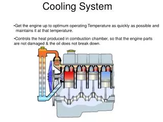
Fourier Equation for Conduction Heat Transfer • Conduction is one of the heat transfer modes. Concerning thermal design of electronic packages conduction is a very important factor in electronics cooling specially conduction in PCB’s and chip packages. • The basic law governing the heat transfer by conduction is Fourier’s law
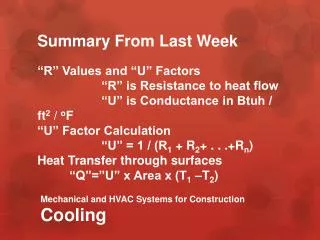
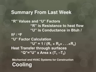
Energy Equation As a system, energy balance may be applied on any electronic component. A typical energy balance on a control volume can be described as shown in the following equation. And the amount of energy flowing into or out of the system can be described by the Fourier’s law.
Energy Equation in Cartesian Coordinates • For a constant thermal conductivity the heat equation could be rewritten as Where α = k/ ρ Cp is the thermal diffusivity.
One dimensional steady state conduction without heat generation • The assumptions made for this kind of analysis are: - One dimensional - Steady state - No heat generation - Constant material properties
One dimensional steady state conduction in Cartesian coordinates without heat generation
One dimensional steady state conduction in cylindrical coordinates without heat generation Considering the assumptions stated before, dT/dr is constant and heat flow only in one spatial coordinates the general form becomes, Where subscripts 1 and 2 refer to the inner and the outer surfaces respectively.
One dimensional steady state conduction with uniform heat generation • The assumptions made for this kind of analysis are: - One dimensional - Steady state - Uniform heat generation - Constant material properties
One dimensional steady state conduction in Cartesian coordinates with uniform heat generation q =q''' ×A × L = Ts – Tc/(Lc/kc Ac)
One dimensional steady state conduction in cylindrical coordinates with uniform heat generation T = Ts + q''' / 4k( ro2 – r2 ) For a convective boundaries T = T∞ + q''' / 4k( ro2 – r2 ) + q''' ro/ 2h
Extended surfaces (Fins) From the rate equations, it is clear that enhancing heat transfer could be done by several methods: - Increasing the temperature difference - Increasing the heat transfer coefficient - Increasing the surface area A , Fins are used to add a secondary surface to the primary surface and thus increasing the heat transfer area. In electronic equipment cooling straight rectangular fins are mostly used and are done of good conducting material to attain the root temperature through the fins in order to increase the heat transferred. Fins used in electronics cooling are usually used of aluminum and are quite thin about 1.3 to 1.5 mm thick.
Extended surfaces (Fins) In electronics cooling fins are usually considered to have an insulated tip. The heat transferred by fins are expressed in its effectiveness which is defined as ηf = qf / qmax where qf is the heat actually transferred by the fin and qmax is the maximum heat that could be dissipated by the fin (i.e. when the fin has a uniform temperature equals to the root temperature tr.
Extended surfaces (Fins) ηf = (tanh ml )/ml Where m = and l and b are defined on the fin sketch. Also the fin effectiveness could be considered as the fraction of the total surface area of the fin Af that is effective for the heat transfer by convection maintained at root temperature tr. ηf = Af, eff/Af,tot q = h [( Atot – Af) + ηf Af] (tr- ta) = ηo Atot h (tr- ta) Where ηo = 1 – (Af/Atot) (1- ηf ) If the fin is of convective tip a correction could be done as lc= l + (t/2)
Fin Geometries Fin descriptions
Introduction • Natural or free convection occurs due to the change in density of the fluid caused by heating process in a gravity field • The natural convection is the most common method used in electronics cooling; there is a large class of equipment that lends itself to natural convection . • The general equation to define the convective heat transfer either forced or free is given by the Newton's law of cooling:
The convection heat transfer coefficient (h) • h is expressed by the dimensionless Nusselt number (Nu) which is related to the dimensionless ratios Grashof (Gr) and Prandtl (Pr) numbers or the Rayleigh number (Ra) which is the product of the last two dimensionless groups.
Empirical correlations for free convection • All the average free-convection heat-transfer coefficients for external flow can be summarized in the following expression - The constants c, m are given in table 7.1 for the uniform surface temperature case .The fluid properties are evaluated at mean film temperature (Tf) where Tf = (Ts + T∞)/2. - The characteristic length for different geometries is: - vertical plate L = height - Horizontal plate L = W/2 ,W = width - Spheres L = D - Horizontal tube L = D - Vertical tube - If: L = length (L) - If not. L = D
Free convection over horizontal plates • For uniform surface temperature (TS = constant) - We have many cases for horizontal plates with constant surface temperature as shown in Figure • (a) Lower surface of heated plates • (b) Upper surface of heated plates • (c) Lower surface of cooled plates • (d) Upper surface of cooled plates
Free convection over horizontal plates with uniform surface temperature • For lower surface of heated plates or upper surface of cooled plates • For upper surface of heated plates or Lower surface of cooled plates - Where fluid properties are evaluated at mean film temperature Tf = (Ts + T∞)/2
Natural convection from finned surfaces • The amount of heat that can be removed from an electronic component that is cooled by natural convection will be substantially increased if the surface area of the component can be substantially increased. One convenient method for increasing the surface area is to add fins as shown in Figure, with a low thermal resistance, the temperature of the fins will then be nearly equal to the surface temperature of the electronic component. The additional heat transfer to the atmosphere will be proportional to the increase in the surface area. • Fins will increase the size and weight of the electronic component. This may be a small penalty to pay if the cost is reduced and the reliability is increased by eliminating the need for a cooling fan.
Natural convection from finned surfaces • The effectiveness of the finned surface will depend upon the temperature gradient along the fin as it extends from the surface of the electronic component. When the fin has a small temperature gradient, the temperature at the tip of the fin will be nearly equal to the temperature at the base of the fin or the chassis surface, and the fin will have a high efficiency. The natural convection coefficient must be corrected to give the effective heat transfer coefficient (heff) due to fins - And the effective heat transfer coefficient is: - Then the total heat transfer divided into two components due to the heat transferred from the free exposed surface of the electronic component, and the heat transferred from fins surface.
Boundary layer over a flat plate Flow of a fluid over a flat plate with laminar, transition, and turbulent boundary layers.
Forced convection correlations • Flow over flat plate • With a fluid flowing parallel to a flat plate we have several cases arise: - Flows with or without pressure gradient - Laminar or turbulent boundary layer - Negligible or significant viscous dissipation (effect of frictional heating) • Flow over cylinders, spheres, and other geometries • Heat transfer across tube banks • Heat transfer with jet impingement • Internal Flows (inside tubes or ducts)
Cylinders The empirical relation represented by Hilpert given below is widely used, where the constants c, m are given in Table 9.1, all properties are evaluated at film temperature Tf Constants of c and m at different Reynolds numbers
Other geometries Constants for Equation 9.24 for non circular cylinders external flow
Heat transfer across tube banks Heat transfer through a bank (or bundle) of tubes has several applications in industry as heat exchanger which can be used in many applications. When tube banks are used in heat exchangers, two arrangements of the tubes are considered aligned and staggered as shown in Figure 3. If the spacing between the tubes is very much greater than the diameter of the tubes, correlations for single tubes can be used. Correlations for flow over tube banks when the spacing between tubes in a row and a column are not much greater than the diameter of the tubes have been developed for use in heat-exchanger applications will be discussed as follows. Figure 9.3 arrangements of the tubes (a) In-line arrangement, (b) staggered arrangement
Heat transfer across tube banks For the average convective heat transfer coefficient with tubes at uniform surface temperature, experimental results carried by Zukauskas (1987) recommended the following correlation: a = ST /D; b = SL /D. ST = Transverse pitch; SL = Lateral pitch D = tube diameter All properties are evaluated at the arithmetic mean of the inlet and exit temperatures of the fluid (T∞i + T∞o)/2, except PrSwhich is evaluated at the surface temperature TS. The values of the constants c, p, m, and n are given in Table 9.4 for in-line arrangement and
Heat transfer across tube banks In-Line arrangement values of constants in Equation (9.25) (p = 0 in all cases) staggered arrangement values of constants in Equation (9.25)
Heat transfer with jet impingement • Cooling analysis: • Free single phase jet impingement cooling is affected with many variables such as: • Jet diameter (d) • Fluid velocity (v) • Jet to heated surface distance (H ) • Size of heated surface area (L x L) • Coolant properties • The average heat transfer coefficient correlation is given by Jigi and Dagn • The properties are evaluated at mean film temperature (TS + T∞)/2 • This correlation is experimented for FC-77 and water and also valid for 3< H/d <15 • 3< H/d <15 • d = 0.508 to 1.016 mm • v < 15 m/s • small surface dimensions L<12.7 mm (microelectronic devices)
Internal Flows (inside tubes or ducts) The heat transfer to (or from) a fluid flowing inside a tube or duct used in modern instruments and equipments such as laser coolant lines ,compact heat exchanger , and electronics cooling (heat pipe method). Only heat transfer to or from a single-phase fluid is considered. The fluid flow may be laminar or turbulent, the flow is laminar if the Reynolds number (rumDH/m) is less than 2300 (Re ≤ 2300), based on the tube hydraulic diameter (DH = 4A / P) where A, P is the cross sectional area and wetted perimeter respectively and um is average velocity over the tube cross section. Also the hydraulic diameter should be used in calculating Nusselt number. And If the Reynolds number is greater than 2300 the flow is turbulent (Re >2300).
Internal Flows (inside tubes or ducts) Heat transfer correlations
Introduction The electromagnetic waves travel through any medium or in vacuum at the speed of light (c), which equals 3 × 10⁸ m/sec. This speed equal to the product of the wave length l and frequency ν c = λν The metric unit for the wave length λ is centimeters or angstroms (1 angstrom = 10-8 centimeter). A portion of the electromagnetic spectrum is shown in figure.
Blackbody radiation Materials used in electronic hard ware may be classified either as black or gray surfaces. A rough or finned surface has higher emittance than the same surface when it is smooth or unfinned. In both cases the emittance increases because the surfaces have many small cavities. These cavities act as many small partial black bodies. A small hole in a hollow sphere is often used to represent a black body. The energy enters the small opening and strikes the opposite wall, where part of the energy is absorbed and part is reflected. The reflected energy again strikes the opposite wall, where part of the energy is absorbed and part is reflected. This process continues until all of the energy is absorbed, as shown in the next figure. Constructing a Black body enclosure
Blackbody radiation Integration yields; Eb = σT4 Where the temperatures in the Kelvin's and the Stefan-Boltzmann constant (σ) has the numerical value σ = 5.67 x 10⁻⁸ W/m2.k The next figure shows the spectral emissive power Eλ,b as a function of temperature and wavelength, the maximum Eλ,b is corresponding to wave length λmax The nature of this dependence may be obtained by differentiating with respect to λ and setting the result equal to zero, we obtain (λmax × T) = 2897.6 μm.k The above equation is known as Wien's displacement law
Radiation properties of surfaces Reflectivity Absorptivity Transmissivity Emissivity
Special cases for two gray surfaces (d) Small body in large enclosure: A1/A2 ≈ 0 By applying summation rule : F12 = 1
Radiation shields If it is desired to minimize radiation heat transfer between two surfaces, it is a common practice to place one or more radiation shields between them as shown in figure. These shields do not deliver or remove any heat from the overall system; they only place another resistance in the heat flow path so that the overall heat transfer is retarded.