Download
1 / 68
830 likes | 1.09k Views
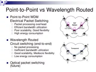
Chapter 6 Bandwidth Utilization: Multiplexing and Spreading. Note. Bandwidth Utilization. Bandwidth utilization is the wise use of available bandwidth to achieve specific goals. Efficiency can be achieved by multiplexing; privacy and anti-jamming can be achieved by spreading.

E N D
Chapter 6 Bandwidth Utilization: Multiplexing and Spreading
Note Bandwidth Utilization Bandwidth utilization is the wise use of available bandwidth to achieve specific goals. Efficiency can be achieved by multiplexing; privacy and anti-jamming can be achieved by spreading.
6.1 MULTIPLEXING Whenever the bandwidth of a medium linking two devices is greater than the bandwidth needs of the devices, the link can be shared. Multiplexing is the set of techniques that allows the simultaneous transmission of multiple signals across a single data link. As data and telecommunications use increases, so does traffic. Topics discussed in this section: Frequency-Division MultiplexingWavelength-Division MultiplexingSynchronous Time-Division Multiplexing Statistical Time-Division Multiplexing
Multiplexing • Dividing a link into channels • Word link refers to the physical path • Channel refers to the portion of a link that carries a transmission • between a given pair of lines.
Multiplexing • Multiplexing • is the set of techniques that allows the simultaneous transmission of multiple signals across a single data link.
FDM • Multiplexer • transmission streams combine into a single stream(many to one) • Demultiplexer • stream separates into its component transmission(one to many) and directs them to their intended receiving devices
FDM • FDM (Frequency-Division) FDM is an analog multiplexing technique that combines analog signals.
FDM (cont’d) • FDM process • each telephone generates a signal of a similar frequency range • these signals are modulated onto different carrier frequencies(f1, f2, f3)
FDM(cont’d) • FDM multiplexing process, frequency-domain 0 4 20 24 00 0 4 24 28 20 32 0 4 28 32
FDM (cont’d) • FDM multiplexing process, time-domain
FDM(cont’d) • Demultiplexing • separates the individual signals from their carries and passes them to the waiting receivers.
FDM(cont’d) • FDM demultiplexing, frequency-domain 20 20 24 0 4 24 0 4 24 28 20 32 28 28 32 0 4
FDM(cont’d) • FDM demultiplexing process, time-domain
Example 6.1 Assume that a voice channel occupies a bandwidth of 4 kHz. We need to combine three voice channels into a link with a bandwidth of 12 kHz, from 20 to 32 kHz. Show the configuration, using the frequency domain. Assume there are no guard bands. Solution We shift (modulate) each of the three voice channels to a different bandwidth, as shown in Figure 6.6. We use the 20- to 24-kHz bandwidth for the first channel, the 24- to 28-kHz bandwidth for the second channel, and the 28- to 32-kHz bandwidth for the third one. Then we combine them as shown in Figure 6.6.
FDM(cont’d) Figure 6.6 Example 6.1
Example 6.2 Five channels, each with a 100-kHz bandwidth, are to be multiplexed together. What is the minimum bandwidth of the link if there is a need for a guard band of 10 kHz between the channels to prevent interference? Solution For five channels, we need at least four guard bands. This means that the required bandwidth is at least 5 × 100 + 4 × 10 = 540 kHz, as shown in Figure 6.7.
FDM(cont’d) Figure 6.7 Example 6.2
Example 6.3 Four data channels (digital), each transmitting at 1 Mbps, use a satellite channel of 1 MHz. Design an appropriate configuration, using FDM. Solution The satellite channel is analog. We divide it into four channels, each channel having a 250-kHz bandwidth. Each digital channel of 1 Mbps is modulated such that each 4 bits is modulated to 1 Hz. One solution is 16-QAM modulation. Figure 6.8 shows one possible configuration.
Figure 6.8 Example 6.3 FDM(cont’d)
FDM(cont’d) • Example : Cable Television • coaxial cable has a bandwidth of approximately 500Mhz • individual television channel requires about 6Mhz of bandwidth for transmission • can carry 83 channels theoretically
Analog Hierarchy To maximize the efficiency of their infrastructure, telephone companies have traditionally multiplexed signals from lower bandwidth lines onto higher bandwidth lines.
Example 6.4 The Advanced Mobile Phone System (AMPS) uses two bands. The first band of 824 to 849 MHz is used for sending, and 869 to 894 MHz is used for receiving. Each user has a bandwidth of 30 kHz in each direction. How many people can use their cellular phones simultaneously? Solution Each band is 25 MHz. If we divide 25 MHz by 30 kHz, we get 833.33. In reality, the band is divided into 832 channels. Of these, 42 channels are used for control, which means only 790 channels are available for cellular phone users.
Wavelength Division Multiplexing (WDM) • WDM is conceptually same as FDM • except that the multiplexing and demultiplexing involve light signals transmitted through fiber-optic channels
WDM (cont’d) WDM is an analog multiplexing technique to combine optical signals. λ1 λ1 λ2 λ2 λ3 λ3 Very narrow bands of light from different sources are combined to make a wider band of light λ3 + λ1 λ2 +
WDM (cont’d) • Combining and splitting of light sources are easily handled by a prism • Prism bends a beam of light based on the angle of incidence and the frequency. • One application is the SONET.
TDM • TDM(Time-Division Multiplexing) • is a digital process that can be applied when the data rate capacity of the transmission medium is greater than the data rate required by the sending and receiving device DM is a digital multiplexing technique for combining several low-rate channels into one high-rate one.
TDM(cont’d) • Time-Division Multiplexing • is a digital process that allows several connections to share the high bandwidth of a link, time is shared. • Two different schemes : Synchronous TDM & Statistical TDM
TDM(cont’d) Figure 6.13 Synchronous time-division multiplexing UNIT UNIT Time slot(T/3 sec) In Synchronous TDM, the data rate of the link is n times faster, and the unit duration is n times shorter.
Example 6.5 In Figure 6.13, the data rate for each input connection is 1 kbps. If 1 bit at a time is multiplexed (a unit is 1 bit), what is the duration of (a) each input slot, (b) each output slot, and (c) each frame? Solution We can answer the questions as follows: a.The data rate of each input connection is 1 kbps. This means that the bit duration is 1/1000 s or 1 ms. The duration of the input time slot is 1 ms (same as bit duration).
Example 6.5 (continued) b.The duration of each output time slot is one-third of the input time slot. This means that the duration of the output time slot is 1/3 ms. c.Each frame carries three output time slots. So the duration of a frame is 3 × 1/3 ms, or 1 ms. The duration of a frame is the same as the duration of an input unit.
Example 6.6 Figure 6.14 shows synchronous TDM with a data stream for each input and one data stream for the output. The unit of data is 1 bit. Find (a) the input bit duration, (b) the output bit duration, (c) the output bit rate, and (d) the output frame rate. • Solution • We can answer the questions as follows: • a.The input bit duration is the inverse of the bit rate: 1/1 Mbps = 1 μs. • b.The output bit duration is one-fourth of the input bit duration, or ¼ μs.
Example 6.6 (continued) c.The output bit rate is the inverse of the output bit duration or 1/(1/4μs) or 4 Mbps. This can also be deduced from the fact that the output rate is 4 times as fast as any input rate; so the output rate = 4 × 1 Mbps = 4 Mbps. d.The frame rate is always the same as any input rate. So the frame rate is 1,000,000 frames per second. Because we are sending 4 bits in each frame, we can verify the result of the previous question by multiplying the frame rate by the number of bits per frame.
TDM(cont’d) Figure 6.14 Synchronous TDM Example 6.6
Example 6.7 Four 1-kbps connections are multiplexed together. A unit is 1 bit. Find (a) the duration of 1 bit before multiplexing, (b) the transmission rate of the link, (c) the duration of a time slot, and (d) the duration of a frame. Solution We can answer the questions as follows: a. The duration of 1 bit before multiplexing is 1 / 1 kbps, or 0.001 s (1 ms). b.The rate of the link is 4 times the rate of a connection, or 4 kbps.
Example 6.7 (continued) c.The duration of each time slot is one-fourth of the duration of each bit before multiplexing, or 1/4 ms or 250 μs. Note that we can also calculate this from the data rate of the link, 4 kbps. The bit duration is the inverse of the data rate, or 1/4 kbps or 250 μs. d.The duration of a frame is always the same as the duration of a unit before multiplexing, or 1 ms. We can also calculate this in another way. Each frame in this case has four time slots. So the duration of a frame is 4 times 250 μs, or 1 ms.
Synchronous TDM(cont’d) • Interleaving • Synchronous TDM can be compared to a very fast rotating switch • Switches are synchronized and rotate at the same speed, but in opposite directions. • On the multiplexing side, as the switch opens in front of a connection, that connection has the opportunity to send a unit onto the path. • This process is called INTERLEAVING. • On the demultiplexing side, as the switch opens in front of a connection, that has the opportunity to receive a unit from the path.
Synchronous TDM (cont’d) • Empty Slots • If a source does not have data to send, the corresponding slot in the output frame is empty.
Synchronous TDM (cont’d) Example 6.8 Four channels are multiplexed using TDM. If each channel sends 100 bytes/s and we multiplex 1 byte per channel, show the frame traveling on the link, the size of the frame, the duration of a frame, the frame rate, and the bit rate for the link. Solution Frame size : 1byteX4line= Frame rate : Bit rate of the link =100FramesX32bit=
Synchronous TDM (cont’d) Example 6.9 A multiplexer combines four 100-Kbps channels using a time slot of 2 bits. Show the output with four arbitrary inputs. What is the frame rate? What is the frame duration? What is the bit rate? What is the bit duration?
Synchronous TDM (cont’d) Solution Figure 6.17 shows the output for four arbitrary inputs. 20 usec • Frame rate : 100Kbps, 2bits/channel, 100,000b/2=50,000 frame/sec • Frame duration : 1/50,000sec = 2X10⁻⁵sec = 20 usec • Bit rate : bits/frame, 50,000 frames x 8 bits = 400 kbps • Bit duration : 1/400,000sec = 2.5μsec
Synchronous TDM - Data rate Management • How to handle a disparity in the data rates with TDM. • If data rates are not the same, 3 strategies can be used. • Multi-level multiplexing • Multiple-Slot Allocation • Pulse Stuffing
Synchronous TDM - Multilevel multiplexing • Multilevel multiplexing is a technique used when the data rate of an input line is a multiple of others. • For example, the first two 20khz input lines can be multiplexed together to provide a data rate equal to the last three. • A second level of multiplexing can create an output of 160 kbps.
Synchronous TDM - Multiple-Slot Allocation • Sometime it is more efficient to allot more than one slot in a frame to a single input line. • For example, the input line with a 50-kbps data rate can be given two slots in the output. • We insert a serial-to-parallel converter in the line to make two inputs out of one.
Synchronous TDM - Pulse Stuffing • Sometime the bit rates of sources are not multiple integers of each other. • Pulse stuffing is to make the highest input data rate the dominant data rate and then add dummy bits to the input lines with lower rates. • This technique is called Pulse stuffing, bit padding, or bit stuffing.
Synchronous TDM (cont’d) • Framing Synchronizing • If the multiplexer and the demultiplexer are not synchronized, a bit belong to one channel may be received by the wrong channel. • Framing bits allow the demultiplexer to synchronize with the incoming stream so that it can separate the time slots accurately. • In most cases, this synchronization bits are added to the beginning of each frame, and synchronization information consists of 1 bit per frame, alternating between 0 and 1.(ex: 10101010 ….) Fig 6.22
Synchronous TDM (cont’d) • Example6.10 • Date rate of each source : 250 x 8 = 2000bps = 2kbps • Duration of a character: 1/250 sec or 4 ms • Frame rate: 250frames/sec • Duration of each frame: 1/250s or 4 ms • No. of bits per frame: 4 charaters + 1 extra sync bit = 33 bits • Date rate of link: 250 x 33 bits, or 8250 4 characters + 1 framing bit
Example 6.11 Two channels, one with a bit rate of 100 kbps and another with a bit rate of 200 kbps, are to be multiplexed. How this can be achieved? What is the frame rate? What is the frame duration? What is the bit rate of the link? Solution We can allocate one slot to the first channel and two slots to the second channel. Each frame carries 3 bits. The frame rate is 100,000 frames per second because it carries 1 bit from the first channel. Frame duration is 1/100,000s or 10μs. The bit rate is 100,000 frames/s × 3 bits per frame, or 300 kbps.
Digital Signal Service • DS(Digital Signal) Service - Digital Hierarchy • advantage - less sensitive than analog service to noise - lower cost
Multiplexing application(cont’d) • DS Service • DS-0 : single digital channel of 64Kbps • DS-1 : 1,544Mbps, 24 x 64Kbps + 8Kbps (overhead) • DS-2 : 6,312Mbps, 96 x 64Kbps+168Kbps (overhead) • DS-3 : 44,376Mbps, 672 x 64Kbps+1.368Mbps (overhead) • DS-4 : 274,176Mbps, 4032 x 64Kbps+16.128Mbps (overhead)
Multiplexing application(cont’d) Table 6.1 DS and T line rates 376