Download
1 / 30
310 likes | 485 Views
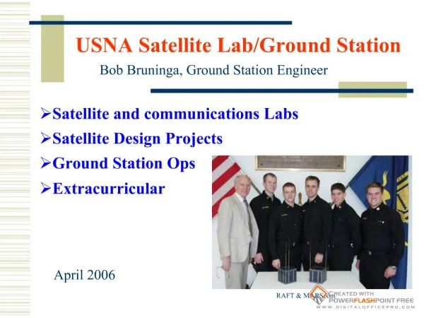
May 10-07 Client: Matthew Nelson Advisor: John Basart Team: Karl Deakyne, SungHo Yoon, Luke Olson. Cyclone Satellite (CYSAT). Ground Station for Satellite Operation ( CySat ). Project Plan. Overall goal: Ground Station for CySat Team Fick Observatory, Dish Antenna

E N D
May 10-07 • Client: Matthew Nelson • Advisor: John Basart • Team: Karl Deakyne, SungHo Yoon, Luke Olson Cyclone Satellite (CYSAT) Ground Stationfor Satellite Operation(CySat)
Project Plan • Overall goal: • Ground Station for CySat Team • Fick Observatory, Dish Antenna • High sensitivity receiving • Automatic Tracking • Previous Team: • Dish control from computer • Build 440 MHz Sub reflector • Rotary Encoders for tracking dish position • Our team: • Ensure strength and signal to noise ratio of received signal is adequate • Tracking
Requirements • Functional • The system shall be able to receive a signal that is sent from an orbiting satellite with a sent power of 1W (or 3 dBm) and the signal should be easily recognizable by a standard radio located in the observatory • The system shall be able to automatically track an orbiting satellite • Non-Functional • The system shall fit inside the dish • The system shall be weatherproof
Project Plan • Work Breakdown • Luke • Develop Tracking Software • SungHo, Karl • Design and Build Front-End
Design – Front End • Calculations – Without modification • Analysis: • Signal-to-Noise Ratio = -109.11dBm – (-126.27dBm) = 8.68 dB • (Input power) - (Sensitivity) = 6.99 dBm • These numbers do not yet meet the specifications! • Solution: Front-End Box for amplification
Design Front-End Progression First Full Parts Design 3
Design Front-End Progression Design Before Purchasing Parts
Band Pass Filter • Problems with BPFs • Commercial filters not perfect for our range • Custom filter not immediately available • Solutions • Considered putting LPF and HPF in series • Advised advised to continue without BPFs, but to leave room for eventual installation • Effects • Radio filters around center frequency • Pre-filtering desirable, but not necessary • Slight decrease in SNR, but this is negligible
Design Front End Progression Final Design Apr 2010 5
Design – Tracking Software • Requirement: • Automatically track an orbiting satellite • Solution: • Pull azimuth and elevation from Ham Radio Deluxe • Track the position of the dish with existing rotary encoders • Move dish through an Ethernet connection with the motor control microcontroller
Implementation –Tracking Software • Java Based Application • GUI • Allows user to manually control dish, track a satellite, and set calibration settings • Data Monitoring • Two Threads • DDEThread: Continuously pulls azimuth and elevation from Ham Radio Deluxe, using Dynamic Data Exchange • DishPositionThread: Monitors the rotary encoders to track the azimuth and elevation of the dish • Calibration • Automatic Calibration to ensure accurate tracking
Required Specifications • Amplifier • 440 MHz Low Noise Amplifier • Low noise figure (<3) • Moderate gain (~20dB) • Switch • Must work at 440 MHz, minimal losses • High Power Rating (~10W) • Electrically controlled • Filter • Design Frequency, 440 MHz • Filters out harmonics • Low power • Radio • High Sensitivity • Low Cost
Device Specifications • 881-CCR-33S6O(Switch) • Loss at 440 MHz < .4 dB • Power Rating at 440 MHz = 100W CW • Electrically controlled • ZX60-33LN+ (LNA) • Low noise Amplifier • Low noise figure = 1.1 • Gain = 21.3 dB @ 440MHz • Filter • Too costly to get device within specification • Radio • Too costly for budget, the CySat team will have to provide the radio • Our Recommendation: • Icom 208H • Sensitivity = • .18 uV, -37dBm • Cost = $310
Calculations – With Front-End • Analysis: • Signal-to-Noise Ratio (at Satellite Dish) = -109.11dBm – (-126.27dBm) = 17.16 dB • Power into the Radio > Radio Sensitivity : Radio is able to decode the input signal. • (Input power) - (Sensitivity) = 23.0 dBm
Test Plan • Individual Part Testing • Front-End Testing • Tracking Software prototyping • Overall System Evaluation and Testing
Test • Place:SSCL Lab at Howe Hall • Devices: • Signal Generator (Model: ) • Spectral Analyzer (Model: ) • DC Voltage Generator (Model: ) • Methods: • RF Switches • Apply 440MHz signal to the input of switch, using a signal generator. • Change 0 DCV to 12 DCV supplied to switches. • Observe if signal path is changed from “Normally Closed” to “Normally Open”. • Low Noise Amplifier (LNA) • Apply 440MHz signal to LNA. • Connect into spectral analyzer • Observe if the incoming signal is amplified as we expected. • Whole Front-End System • Combine two methods above. • Checkpoints: • if switches are working properly depending on voltage change. • if the amplifier(LNA) is working properly as we expected. RF Switch LNA
Test Results • Switch Test (Model: Mouser CCR-33SC-N) • Signal(440MHz): 10.26 dBm • Noise power: -50 ~ -80 dBm Normally Open Normally Closed • Conclusion: Verified its switching operation
Test Results • Low Noise Amplifier (Mini-circuits ZX60-33LN+) Input Output Center frequency: 440MHz Magnitude of Signal: -58.6dBm Center frequency: 440MHz Magnitude of signal: -38.1dBm • Experimental Gain: 20.5 dB • Expected Gain: 21.1 dB • Conclusion: Similar gain as expected
Test Results • Whole Front-End System • Testing Frequency: 439.9MHz • Signal In: -39.9dBm • Signal Out: -21.43dBm • Experimental Gain from the system: 18.47 dB • Expected Gain: 16.01 dB • Analysis • Better Gain than expected • Gain Error reasoning: • Gain and loss in parts’ manual are less accurate for 440MHz. • Conclusion: The whole system is working as expected.
Prototyping/Testing – Tracking Software • Ham Radio Deluxe Test
Prototyping/Testing – Tracking Software • Motor Control Test • Tested with microcontroller
Evaluation of Overall System • Ideally • Install sub reflector • Install front-end box • Install software • Test entire system with orbiting satellites • Train CySat on how to use the system • But…
Evaluation of Overall System • Issues • During winter the dish was frozen • Unable to do anything until March • In March we discovered that the dish does not move up/down • Numerous trips to the Fick Observatory to attempt to fix issue failed • Rotary Encoders are only partially installed, can’t install them until the dish moves down • Can’t install sub reflector or front-end box until dish can be moved down
Conclusions • Implemented systems that we designed • Unable to successfully implement final product, due to unforeseen issues at the Fick Observatory • Future work: • Fix issues at Fick Observatory • Motor Control • Rotary Encoders • Install Sub-reflector, front-end box