Download
1 / 27
270 likes | 361 Views
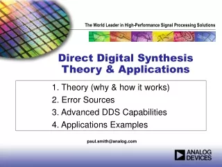
Design and Applications of Direct-Digital VFOs. By James D. Hagerty. What is DDS?. Generates a waveform using digital hardware building blocks. The DDS output frequency is referenced to a high-stability clock signal (user-provided). Avoids L’s and C’s!

E N D
Design and Applications of Direct-Digital VFOs By James D. Hagerty
What is DDS? • Generates a waveform using digital hardware building blocks. The DDS output frequency is referenced to a high-stability clock signal (user-provided). Avoids L’s and C’s! • Change frequency “on the fly” by serially loading 32-bit binary numbers into the chip • High degree of accuracy and software flexibility; control with a microprocessor or PC
Simple DDS Architectures • Most Basic Configuration: Clocked Lookup Table (Addresses Memory with Stored Values) Clock Signal Table of Sampled Sine Values Address Counter Clocked Register Fc N Bits D/A Converter Fout From, “A Technical Tutorial on Digital Signal Synthesis,” Analog Devices, C. 1999.
More Flexible DDS (adds a phase accumulator) PHASE ACCUMULATOR Phase Register Phase-to- Amplitude Converter Tuning Word Fout D/A Converter Summer Data Bus 16 bits Data Bus 16 bits 32 bits Data Bus 16 bits System Clock From: “A Technical Tutorial on Digital Signal Synthesis,” Analog Devices, C. 1999.
Direct-Digital VFO • System Architecture (May 2008 QEX) Master Clock AD9951 DDS 30 MHz LPF 30 MHz LPF Fout 20 dB 100-150 MHz 0.5 volts peak @ 50 ohms Control Signals DISPLAY Microprocessor Shaft Encoder Switch Closures (CAL, RIT, Memory, SAVE, Offset, etc.)
DDS Control Signals CONTROL FLOW PowerDownCtrl Reset OSK DATA SDIO Data Clock SCLK Data Start/Stop I/O Update Microprocessor DDS
Shaft Encoder Timing • Grayhill, Bournes, etc. shaft encoder pulses “1” “1” “0” “0” “1” CHANNEL A “0” “1” “1” “0” “0” CHANNEL B Quadrature 2-bit codes; Channel A leads Channel B by 90 degrees ONE CYCLE
Frequency Tuning Word • 32-bit fixed-point integer stored in hexadecimal (base-16!) format. • Ftune= {(2**32)/Fclock} * Fout ; “Master Equation!” • Example: for a 7 MHz output, Ftune = {(4.295 x 10E9) /150 MHz} x 7 MHz = 200.431 E6 (base 10) = BF258BF in hex (base 16) Note: if Fclock= 134.217728 MHz, coefficients are perfect integers (no rounding/truncation error!).
DDS Clock Signal • Typically 100-150 MHz for the AD9951 • Can use clock multiplier (internal (x 4) to (x 20) PLL in chip); generate up to 144 MHz signal! • Clock multiplier gives higher clock to carrier ratio at the expense of phase noise. • AD9951 rated for a 400 MHz clock rate, but will reliably clock at 500 MHz (proto running at 536.87 MHz!); can generate VHF signals Clock signal should be stable, and as spectrally pure as possible. 25-50 ppm most common Avoid multipliers inside the clock itself; extra phase noise! See photo.
Phase Noise • The single most important parameter limiting weak-signal communications: (Hayward, Rohde, etc.) • Close-in time-domain jitter produces adjacent sideband energy that is very hard to filter out. • Specified as dBc (dB down from the carrier level) at a reference carrier frequency • Often specified 10 kHz away from the carrier • Typical commercial local oscillator: (-130 to (-140 dBc) phase noise levels (see Sherwood Engineering web site for typical specs)
Important Features • CAL- freezes display and adds or subtracts 1 Hz steps to frequency register; can then save in flash memory. RIT: tunes plus/minus 10 kHz of displayed carrier in 10 Hz steps. Can save in EEPROM. Memory channels: 16/expandable to 32; saves all frequency settings including RIT Offset: Two offsets, plus or minus, ON/OFF
PC Layout • Want to separate noisy digital circuitry from low-noise analog portion; Where Do the Currents Flow? • Keep leads as short and direct as possible • Use as few vias as possible, especially in high-speed lines (can act as VHF tank circuits!) • Separate analog and digital planes, connected at edge of card (multiple PCB layers) • Can use digital decouplers (ADUM1100) to break noisy circuit paths (i.e., microprocessor crystal!) • Re. Silicon Labs Application Note AN203
APPLICATIONS IDEAS • Rotary-Switched Band Switched DDS VFO • Driving a “Boat Anchor” Tube Rig • Other Topics of Interest
Rotary Band-Switched DDS DDS Control Lines 74HC147 Priority Encoder Band Switch Micro-processor 4-bit digital word Encoder Inputs Pulled Up To +5 volts (via pullup resistors)
Driving a “Boat Anchor” Mostly an Impedance-Matching Problem Need Volts, as Opposed to “Watts” Need High Output Impedance Driver High Output Impedance Makes Driver More Sensitive to Cable Loading Grid Circuit Can Become Non-Linear; Assume At Least Several K-Ohms of Grid Input Impedance for Practical Circuits Must Preserve Loaded Stability of Drive Amplifier
“Boat Anchor Driver” • Published in June 2011 CQ; Available on www.WA1FFL.com To Grid, 10-16 volts peak VFO Drive (0.5 Volts peak) Hi-Z 50 Ohms Z LT1227 RF op amp 2N3866 1:4 Broadband Transformer
“Boat Anchors” driven by WA1FFL buffer amp • DX-40, DX-60 • HT-40 • Harvey-Wells Bandmaster • Globe Scout • Valiant 1 • Knight T-60 • QRP “Glowplug” • Millen 90800 • Central Electric Exciter • Drake 2-NT • Can Also Drive Johnson Adventurer & Challenger
Other Topics • Analog Devices Evaluation Boards • AD9854-EVB, AD9954-EVB (has I and Q outputs); control via PC interface for experimentation • New DDS chips: 1-3 GHZ clock rate (AD9910, AD9912, etc.) evaluation boards available; must use clock multiplier! Data sheets now available. • Digital FM Sweep (logic circuit to mimic shaft encoder)