Download
1 / 32
320 likes | 332 Views
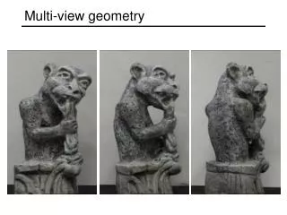
Multi-View Sketching. Learning Objectives. Understand using the ‘Glass Box’ to help define orthographic projections. Be able to define Multi-View Drawing, Projection Plane, the three dimensions, Orthographic Projection. De able to determine if you need one, two or three views

E N D
Learning Objectives • Understand using the ‘Glass Box’ to help define orthographic projections. • Be able to define Multi-View Drawing, Projection Plane, the three dimensions, Orthographic Projection. • De able to determine if you need one, two or three views • Be able to create an Orthographic Projection of a 3-D object.
Multi-View Drawing • Shows two or more two-dimensional views of a three-dimensional object. • Provides the shape description of an object. • When combined with dimensions, serves as the main form of communication between designers and manufacturers.
Example of Multi-view Sketch Dining Chair RIGHT SIDE FRONT LEFT SIDE
Multi-View Drawing All three-dimensional objects have width, height, and depth. • Width is associated with an object’s side-to-side dimension. • Height is associated with an object’s top-to-bottom dimension. • Depth is associated with front-to-back distance.
Multi-View Drawing A typical multi-view drawing includes a top view, a front view and a right side view. TOP VIEW FRONT VIEW RIGHT SIDE VIEW
Orthographic Projection • A technique used to create Multi-View drawings. • Any projection of the features of an object onto an imaginary plane of projection. • The projection of the features of the object is made by lines of sight that are perpendicular to the plane of the feature
Orthographic Projection The best way to understand orthographic projection is to imagine an object contained inside a glass box.
Orthographic Projection There is a total of six glass walls surrounding the object. Each wall represents a projection plane onto which a two- dimensional object view will be created.
Projection Plane Also referred to as a plane of projectionorpicture plane, is an imaginary surface that exists between the viewer and the object. The surface onto which a two-dimensional view of a three-dimensional object is projected and created.
Orthographic Projection Start by focusing only on the front projection plane. A person standing in front of the object would see only the five corners identified in black. 2 3 1 4 line of sight at 90° angle to projection plane 5
Orthographic Projection Projection lines are used to project each corner outward until they reach the projection plane.
Orthographic Projection The visible edges of the object are then identified on the projection plane by connecting the projected corners with object lines.
Checking for Understanding • Go to http://faculty.gvsu.edu/karpenm/melissa/glassboxindex.html • Run through Demonstration of Principles with class • Individually complete Orthographic Projection Tutorial
The Glass Box: 10 MinutesOrthographic Projection Tutorial 2) Select Orthographic Projection Tutorial 3) Experiment with Demo Mode 1) Use the ‘GlassBox’ hyperlink that is on the class website. 4) Complete the levels and the Timed Activities. http://faculty.gvsu.edu/karpenm/melissa/glassboxindex.html
Orthographic Projection The orthographic projection process is then repeated on the other projection planes.
Orthographic View Selection Noteworthy Recommendations for how to select the front view • Most natural position or use • Shows best shape and characteristic contours • Longest dimensions • Fewest hidden lines • Most stable and natural position
Orthographic View Selection No hidden edges Best shape Description BEST FRONT VIEW Most natural position Longest Dimension
Number of Orthographic Projections One View • Uniform thickness or shape • Two views would be identical • All dimensions properly and easily shown on one view Noteworthy
Number of Orthographic Projections Noteworthy Two Views • Symmetrical part • A third view would be identical to one other • Second view is necessary for depth
Sketching a Multi-View Drawing Given the overall dimensions of the object, a pencil, and a sheet of graph paper, a sketching multi-view drawing can be easily done using points, construction lines, and object lines.
Sketching a Multi-View Drawing Step 1 - Boundary Box: Layout the boxes within which the individual views will occur using points and construction lines. TOP Noteworthy FRONT RIGHT SIDE
Sketching a Multi-View Drawing Step 2 - Faces: Use construction lines between the views to indicate the geometry of the views.
Sketching a Multi-View Drawing Step 3 – Faces/Inside: Identify the visible edges with Object lines.
Sketching a Multi-View Drawing Step 4 - Inside:Locate hidden lines.
Historical Example Leonard P. Karr (1913-1995) designed a man-sized hunting blind shaped like a goose called Super Goose, 1991. • How would you label the views presented in the drawing? • Are Mr. Karr’s views properly aligned based on the orientation presented here? • How would you rearrange the views to orient
A Question… Each of the blocks at right has the same overall dimensions and color. What else do they have in common?
A Question… They all have identical top views! Each of the blocks at right has the same overall dimensions and color. What else do they have in common?
Practice on Problem 24: Page 14 In your 2D Sketchbook complete problems 25 – 32 USE YOUR STRAIGHT EDGE!! Don’t erase construction lines. Recall this is a ¼” Grid Step 1 - Boundary Box: Layout the boundary boxes within which the individual views will occur using points and construction lines. Step 2 - Faces/Inside: Use construction lines between the views to indicate the geometry of the views Step 3 - Faces/Inside: Identify the visible edges with Object lines Step 4 - Locate hidden lines
Activity • Complete Drawings 25 – 32. • Start with Baseline one grid (1/4”) up from bottom. • Left vertical line one grid in from left • Make boundary box leaving ¼” between front and top view and ¼” between front and right view. • …