Download
1 / 44
600 likes | 1.36k Views
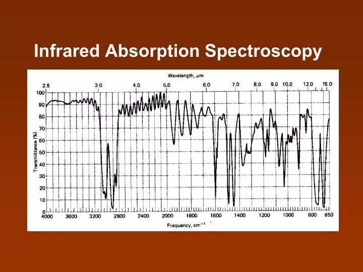
Infrared Absorption Spectroscopy. IR Spectroscopy. deal with the interaction of infrared radiation with matter. IR spectrum (%T against Frequency). chemical nature and molecular structure of cpd. Applications. organic materials polyatomic inorganic molecules organometallic compounds.

E N D
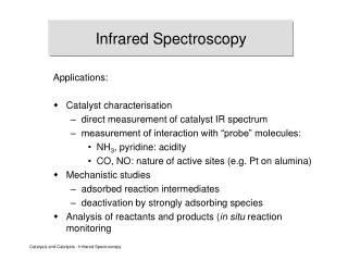
IR Spectroscopy • deal with the interaction of infrared radiation with • matter IR spectrum (%T against Frequency) • chemical nature and molecular structure of cpd Applications • organic materials • polyatomic inorganic molecules • organometallic compounds
IR region of the electromagnetic spectrum • wavelength 770 nm to 1000 mm • (wave number 12,900 to 10 cm-1) IR region is often further subdivided into three subregions • Near-infrared region (nearest to the visible) • Mid-infrared region • Far-infrared region
Table Infrared Spectral Regions wavenumber Range, cm-1 Region Wavelength (l) Range, mm Frequency (v) Range, Hz Near 0.78 to 2.5 12800 to 4000 3.8x10¹⁴ to 1.2x10¹⁴ Middle 2.5 to 50 4000 to 200 1.2x10¹⁴ to 6.0x10¹² Far 50 to 1000 200 to 10 6.0x10¹² to 3.0x10¹¹ Most used 2.5 to 15 4000 to 670 1.2x10¹⁴ to 2.0x10¹³
Mid-infrared region 1. Group-frequency region • wavenumber 4000 to 1300 cm-1 (2.5 to 8 mm) • functional group 2. Finger print region • wavenumber 1300 to 650 cm-1 • เกิดจากโครงสร้างของโมเลกุลที่สมบูรณ์
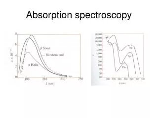
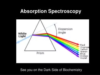
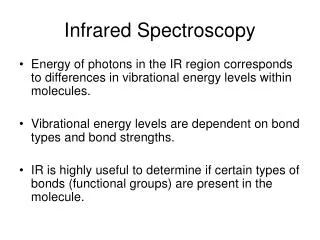
Infrared Spectrometry • useful for quantitative analysis, although it is • considerably more difficult to achieve accurate and • precise results with IR spectrometry than with • UV-visible methods • Beer’s Law provides the basis of quantitative IR • method as it does in UV-visible spectrophotometry Electromagnetic radiation UV-visible electronic transition infrared vibration, rotation
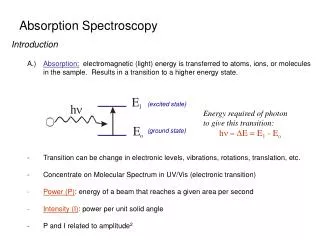
Basis of Infrared Absorption The IR spectrum can be obtained with gas-phase or with condensed-phase molecules. For gas-phase, molecules vibration-rotation spectra are observed. For condensed-phase, the rotaional structure is lost. ‘Vibrational spectroscopy’
2. The frequency of the radiation must satisfy, E = hv, where E is the energy difference between the vibrational states involved 3. The change in vibration must stimulate changes in the dipole moment of the molecule IR active / IR inactive Requirements for the absorption of IR radation 1. The natural frequency of vibration of the molecules must equal the frequency of the incident radiation
Types of Molecular Vibrations IR Vibration of bonds • Stretching • Bending Stretching vibration เกี่ยวข้องกับการเปลี่ยนแปลงความยาวระหว่างอะตอม ที่เกิดพันธะกัน • Symmetric stretching • Asymmetric stretching
Methylene Symmetric stretching (~2853 cm-1) Asymmetric stretching (~2926 cm-1)
Bending vibration การเปลี่ยนแปลงมุมระหว่างสองพันธะ • Scissoring • Rocking • Wagging • Twisting
In plane Out of plane Bending
Vibrational mode of methylene group
Number of Vibrational Modes Nonlinear molecule Fundamental vibrational modes = 3N-6 Linear molecule Fundamental vibrational modes = 3N-5
Nonlinear molecule: ็H2O Vibrational modes = 3(3) - 6 = 3
Linear molecule: CO2 Vibrational modes = 3N-5 = 3(3)-5 = 4
Molecular Vibration A molecule is made up ofa number of atoms joined by chemical bonds. Such atoms vibrate about each other in the same way as weights held together by springs
Hooke’s Law states that two masses joined by a spring will vibrate such that (1) where = the frequency (rad/sec), but since we have (2)
where = the frequency of vibration, k is the force constant of the bond (N/cm), and is the reduced mass, or (3) where M1 is the mass of one vibrating body, M2 the mass of the other. But is in cyles per second (cps). During this time light travels a distance measured in cm/sec (I.e., the speed of light).
Therefore, if one divides by c, the result is the number of cycle per cm. This is , the wavenumber of an absorption peak (cm-1) and (4) It can be deduced that (5) (6)
Example Calculate the approximate wavenumber and wavelength of the fundamental absorption peak due to the stretching vibration of a carbonyl group C=O The mass of the carbon atom in kg is given by
Similar, for oxygen and the reduced mass m is given by The force constant for the typical double bond is about 1x10³ N/cm. Substituting this value and m into eq. (5) gives
The carbonyl stretching band is found experimentally to be in the region of 1600 to 1800 cm-1 (6.3 to 5.6 mm)
Frequencies of various group vibrations in the group frequency region and in fingerprint region
Instrumentation Three distinct types of instruments employed for IR absorption spectrometry 1. Dispersive instruments with a monochromator are used in the mid-IR region for spectral scanning and quantitative analysis 2. Fourier transform IR systems are widely applied in the far-IR region and becoming quite popular for mid-IR spectrometry
Instrumentation 3. Nondispersive instruments that use filters for wavelength selection or an infrared-absorbing-gas in the detection system are often used for gas analysis at specific wavelength
Block diagram of IR spectrophotometer readout detector source sample monochromator Recorder XY plotter Printer Grating Filter Thermal D Thermocouple Thermopile Thermister Bolometer Pneumatic D Pyroelectric D Nernst Glower Globar Incandescent wire source Hg Arc
IR sources: general • an inert solid that is heated electrically to a • temperature between 1500 and 2200 K • (provide continuous radiant) • the maximum radiant intensity at these • temperatures occurs at between 5000 and 5900 cm-1 • (2 to 1.7 mm)
IR sources The Nernst Glower (Continuous source) • useful and inexpensive source • rare earth oxides formed into a cylinder having a • diameter of 1 to 2 mm and a length of perhaps 20 mm • platinum leads are sealed to the end of the cylinder • to permit passage of electricity; temperatures between • 1200 and 2200 K result • because of a negative temperature coefficient of • resistance, it must be used with ballast resistor in the • heating circuit to prevent burnout
IR sources The Nernst Glower (Continuous source) (cont.) • it is rather fragile, and its lifetime depends on the • operating temperature and the care taken in handling it
IR sources The Nernst Glower (Continuous source)
IR sources The globar (continuous source) • a silicon carbide rod, usually about 50 mm in length • and 5 mm in diameter • current through the globar causes the rod to heat and • emit radiation at temperature exceeding 1000 oC • the power consumption is normally higher than that • of the Nernst Glower • water cooling is needed to cool the metallic electrodes • attached to the rod • less convenient to use and more expensive because • of the necessity for water cooling
IR sources Incandescent wire source • somewhat lower intensity but longer life than • the Globar or Nernst glower • a tightly wound spiral of nichrome wire heated to • about 1100 K by an electrical current • a rhodium-wire heater sealed in a ceramic cylinder • has a similar properties as a source
IR sources The Mercury arc • for the far-infrared region of the spectrum (l> 50 mm) • provide sufficient energy for convenient detection • consist of a quartz-jacketed tube containing mercury • vapour at a pressure greater than one atmosphere • passage of electricity through the vapour forms an • internal plasma source that provides continuous • radiation in the far-infrared region
IR sources The Mercury arc
IR sources The Tungsten filament lamp • the near-infrared region of • 4000 to 12,800 cm-1 • (2.5 to 0.78 mm)
Infrared Detectors General types of infrared detectors: 1. Thermal Detectors Dispersive spectrophotometer 2. Pyroelectric Detectors 3. Photoconducting Detectors Fourier Transform multiplex instrument
Infrared Detectors Thermal Detectors • widely used in the IR region of the spectrum • responses depends upon the heating • effect of radiation Problem: The problem of measuring infrared radiation by thermal means is compounded by thermal noise from surrounding
Infrared Detectors Solution: Thermal detectors are usually encapsulated and carefully shielded from thermal radiation emitted by other nearby objects
Metal A Metal B welded junction (hot) welded junction (cold) Infrared Detectors Thermal detectors: Thermocouples • a thermocouple is made by welding together at • each end two wires made from different metals. • If one welded joint (called the hot junction) becomes • hotter than the other joint (the cold junction), a small • electrical potential develops between the joints
Infrared Detectors Thermal detectors: Thermocouples In IR spectroscopy, the cold junction is carefully screened in a protective box and kept at a constant temperature. The hot junction is exposed to the IR radiation, which increases the temperature of the junction. The potential difference generated in the wires is a function of the temperature difference between the junctions and, therefore, of the intensity of IR radiation falling on the hot junction.
Infrared Detectors Thermal detectors: Thermocouples A well-designed thermocouple detector is capable of responding to temperature difference of 10-6 K. This figure corresponds to a potential difference of about 6 to 8 mV/mW To enhanced sensitivity, several thermocouples may be connected in series to give what a called a ‘thermopile’
Infrared Detectors Thermal detectors: Thermistor/Bolometer A bolometer is a type of resistance thermometer constructed of strips of metals such as platinum or nickel, or from a mixture of metal oxide; the latter devices are sometimes called thermistors. These materials exhibit a relatively large change in resistance as a function of Temperature. The thermistor is normally placed in a bridge circuit with a reference thermistor that is not irradiated. The resistance can be measured by a null-comparison method