Download

1 / 67
740 likes | 967 Views
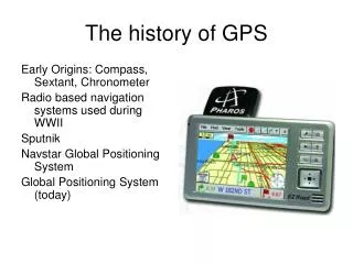
overview of GPS. error sources affecting high accuracy GNSS positioning. What is GPS?. GPS, or Global Positioning System, is able to show you your position on the Earth anytime, in any weather, anywhere. The three parts of GPS are: Satellites Receivers Software. GPS Satellites.

E N D
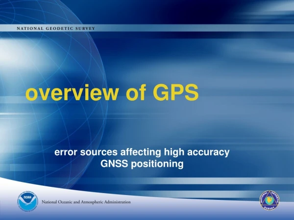
overview of GPS error sources affecting high accuracy GNSS positioning
What is GPS? GPS, or Global Positioning System, is able to show you your position on the Earth anytime, in any weather, anywhere. The three parts of GPS are: • Satellites • Receivers • Software
GPS Satellites The GPS Operational Constellation consists of 24 satellites that orbit the Earth in very precise orbits twice a day. GPS satellites emit continuous navigation signals.
The Signal from the Satellite • Microwave Radio Frequency • Effective Output 500W • Line of Sight • Pass through clouds, glass, plastic • Blocked by buildings, mountains, etc. • Weaker signals under trees
Time Difference The GPS receiver compares the time a signal was transmitted by a satellite with the time it was received. The time difference tells the GPS receiver how far away the satellite is.
Time Delay = Distance • Signal travels at speed of light (c) • Time delay x c = distance • If delay = 0.0682 s then distance = 20,446 km Delay = 68.2 ms
Time Delay = Distance Therefore, we know we are located on a sphere 20,446 km from satellite
3-D Trilateration 1 Satellite 2 Satellites 3 Satellites
Time Correction • Error of 1/1000 second = 300 km • Atomic Clocks used in Satellites • Quartz Clock in GPS receiver • Needs to be corrected • Corrected by seeing fourth satellite
More Satellites are Better • Receiver selects best signal • Geometry affects accuracy • Watch satellite page • If accruing signal from additional satellites good to wait • Able to watch accuracy improve
GPS Signals Each GPS satellite transmits data that indicates its location and the current time. All GPS satellites synchronize operations so that these repeating signals are transmitted at the same instant. Physically the signal is just a complicated digital code, or in other words, a complicated sequence of “on” and “off” pulses.
Signal Components • Almanac (telemetry) updated location of all satellites • Unique Satellite identification code • Pseudorandom noise code – similar to a song Offset = 68.2 milliseconds
The GPS Signals • GPS satellites transmit on two L-band frequencies: • L1 = 1575.42 MHz (19 cm wavelength) • L2 = 1227.6 MHz (24.4 cm wavelength) • These two carrier frequencies (sine waves) are modulated by two digital codes and a navigation message. • Code modulations are achieved by • BPSK (binary phase shift keying) method • QPSK (quadrature phase shift keying) method
The GPS Codes – C/A Code • The Coarse Acquisition (C/A) Code • Modulated on the L1 carrier only • For each satellite, a unique pseudorandom code of 1023 bits • The chip rate is 1.023 Mbps* • In distance domain, one chip is 293 m • Code looks like noise, but is generated mathematically, hence “PRN Code” (pseudorandom noise) • Available to all users * A “chip” is the length of time to transmit 0 or 1 in a binary pulse code. The chip rate is the number of chips per second.
The GPS Codes – P Code • Precision (P) Code • Modulated on both L1 and L2 carriers • Encrypting the P code w/ secret W code results in Y code • Referred to as anti-spoofing (A-S) • Also called P(Y) code • P code chip rate is 10.23 Mbps - 10x faster than C/A • In distance domain, one chip is 29.3 m • P code sequence is very long - A unique pseudorandom noise (PRN) code of 2.35 x 10¹⁴ binary digits • 266 day period; divided into 38 segments of 7 days each • Each satellite transmits a unique 1-week segment of P-code, initialized every Sunday @ 0000
The GPS Navigation Message • Navigation (telemetry) data messages are modulated on both L1 and L2 carriers at a rate of 50 kbps. • In distance domain, one chip is 5950 km • Consists of 25 frames of 1,500 bits each, or 37,500 bits total • Complete transmission takes 750 seconds, or 12.5 minutes • Navigation message includes: • Coordinates of the GPS satellites in time • Satellite health, clock correction, almanac & atmospheric data • Info about other satellites
ExecutionofSurveys;SourcesofError • Errors may be characterized as random, systematic, or blunders • Randomerror represents the effect of unpredictable variations in the instruments, the environment, and the observing procedures employed • Systematicerror represents the effect of consistent inaccuracies in the instruments or in the observing procedures • Blunders or mistakes are typically caused by carelessness and are detected by systematic checking of all work through observational procedures and methodology designed to allow their detection and elimination
GPS Errors & Biases (1) GPS errors include: • Satellite errors • Receiver errors • Signal propagation errors Various schemes can be employed to reduce or even eliminate these errors
GPS Errors & Biases GPS errors include: Satellite errors • orbit error • center-of-mass to L1 antenna phase center • L1-L2 antenna phase center offset • atomic clock error • selective availability (SA) • Satellite geometry, DOP • Transmission multipath • Satellite inter-channel bias
Ephemeris Error • Satellite orbits are modeled (predicted) • Modeling not perfect – Ephemeris error on the order of 2 m to 5 m • Between-receiver differencing does not entirely remove ephemeris error, but better over short baselines (<10 km). • Two receivers located closely see about the same orbit error • In relative positioning, the ratio of ephemeris error to SV range is proportional to the baseline error to baseline length ratio • Expected baseline error is 2.5 mm for a 5 m ephemeris error for a 10 km baseline • Precise ephemeris data can be downloaded and applied during post-processing.
Satellite Clock Errors • Block II/IIA SVs carry 4 clocks • 2 Rubidium and 2 Cesium atomic clocks • Block IIR carry Rubidium clocks only • Ru & Cs clocks are not perfect – some drift • Drift error corresponds to a range error ~2.6 to 5.2 m • Or ~8.6 to 17.3 ns per day • SV time monitored by control segment • Amount of drift is calculated and transmitted in the navigation message • Still leaves an error of several nanoseconds (where one nanosecond equates to a range error of ~ 30 cm) • Best removed by differencing techniques
Selective Availability • SA added by DoD with the Block II SVs in 1990 • Motivated by C/A code receiver accuracies which approached P-code receiver accuracies • Even though P-code designed to be 10x more accurate • SA dithered the SV clock time (delta error) & slowly varied the orbital error (epsilon error) • SA discontinued in 2001 • Too many schemes developed to get around SA • For short baselines, DGPS effectively cancelled SA • Eliminating SA improves autonomous accuracies • 22 m horizontal, 33 m vertical, 95% of the time • DGPS accuracy not improved, but can lower transmission rate of differential correctors
Satellite Distribution When the satellites are all in the same part of the sky, readings will be less accurate.
Satellite Geometry (1) • Good geometry when satellites are spread out • Measures of geometry • DOP – Dilution of Precision (no dimensions) computed from approximate receiver & satellite coordinates • PDOP – Position Dilution of Precision • HDOP – Horizontal Dilution of Precision • VDOP – Vertical Dilution of Precision • TDOP – Time dilution of Precision
Satellite Geometry (2) • The lower the DOP the better • Recommended PDOP < 5 • Recommended HDOP < 2.5 • DOPs are easy to predict using receiver approximate position & ephemeris predictions (SV almanacs).
GPS Errors & Biases GPS errors include: Receiver errors • receiver noise • receiver clock • Antenna phase center • L1-L2 phase center offset • L1-L2 phase center variation • Circular polarization • Receiver inter-channel bias • Stability • Antenna height • Mark stability • Earth tides • Ocean tide loading • Atmospheric loading • Crustal motion
Receiver Clock Errors • Receivers use inexpensive crystal clocks, so experience much larger clock drift. • Can be treated as an unknown in the solution estimation process • Better yet, can be removed with differencing techniques.
ARP MARK ANTENNA HEIGHT The height is measured vertically (NOT slant height) from the mark to the ARP in meters. ARP = Antenna Reference Point, shown at http://www.ngs.noaa.gov/ANTCAL/
phase ctr. ANTENNA TYPE The antenna phase centers are located somewhere around here. The antenna offsets are the distance between the phase centers and the ARP ARP You do not need to know these offsets. They are passed to the processing software through the antenna type The Antenna Reference Point (ARP) is almost always located in the center of the bottom surface of the antenna. Incorrect or missing antenna type big vertical errors
Antenna Phase Center Variation • Phase Center Variation (mm) • Elevation Angle (deg.)
Antenna Phase Center Variation SV 20 SV 20 SV 14 SV 14 . . . . . . . . . . . . Different Phase Patterns Note that SV elevation and varying phase patterns affect signal interpretation differently Antenna Type B Antenna Type A
Antenna Phase Center Variation • The antenna phase center does not coincide with the physical center of the antenna’s active element. • In fact, the phase center can vary with SV elevation and azimuth. • Antenna phase center errors typically on order of a few centimeters.
Antenna Phase Center Variation • Use correct antenna type/calibration parameters for acquisition and processing. • NGS Antenna Calibration web site • For short baseline surveying, use the same antenna on each receiver • Orient each antenna in the same direction • Differencing techniques will cancel phase center variations
GPS Errors & Biases GPS errors include: Signal Propagation errors • Ionospheric effects • Dry troposphere delay • Wet troposphere delay • multipath
Line of Sight Transmissions Line of sight is the ability to draw a straight line between two objects without any other objects getting in the way. GPS transmission are line-of-sight transmissions. Obstructions such as trees, buildings, or natural formations may prevent clear line of sight.
Light Refraction Sometimes the GPS signal from the satellite doesn’t follow a straight line. Refraction is the bending of light as it travels through one media to another.
Ionosphere Greatest at 1400 (local time) Typical 5 to 15 m at zenith Extreme 0.15 to 50 m at zenith Higher frequencies have less effect Error correction by dual frequency “Wet” Troposphere 10% of total effect Model accuracy only 10 to 50% Need humidity along path About 20 cm at zenith Hydrostatic (“Dry”) Troposphere 90% of total effect Model accuracy only 2 to 5% Need surface atmospheric pressure and temperatures Accurate pressure is critical About 2.2 m at zenith AtmosphericErrorSources
Atmosphere based Ionospheric Delay (Advance) Ionosphere > 10 km < 10 km
Ionospheric Delay (1) • The ionosphere is • A region of earth’s atmosphere where uv and x-ray radiation from sun cause gas ionization. • Extends from 50 km to ~1,000 km altitude • Ionosphere is a dispersive medium – it bends GPS signals and changes propagation speed of signal. • Bending (signal refraction) causes negligible range errors • Propagation speed changes cause significant range errors • Speeds up carrier phase beyond speed of light, so ranges appear short • Slows down PRN code, so ranges appear long • Ionosphere is not homogenous – described in layers within which electron densities vary. • Total Electron Count (TEC) varies with time of day, time of year, 11-year solar cycle, geographic location.
Ionospheric Delay (2) • Ionospheric delay is frequency dependant • L2 (1227.6 MHz, 24.4 cm) is greater than L1 delay (1575.42 MHz, 19 cm) • Range errors on the order of 5 to 15 meters, but can be as high as 150 m during extreme solar events at midday and near the horizon • Differencing techniques over short baseline distances can effectively remove much of the ionospheric delay. • Dual-frequency receivers combine L1 & L2 carrier phase measurement for iono-free solutions • But increases measurement noise, so not always reliable • Loose integers of cycle ambiguities • Single frequency receivers must use empirical models in post-processing or from real-time sources.
Troposphere Delay • The more air molecules the slower the signal (dry delay) • High pressure • Low temperature • 90% of total delay • relatively constant and easy to correct for • The more water vapor in the atmosphere the slower the signal (wet delay) • High humidity • 10% of total delay • Highly variable and hard to correct for Ionosphere troposphere
Tropospheric Delay • The troposphere extends from earth’s surface up to about 50 km altitude • It is considered electrically neutral • Non-dispersive medium for RF below 15 GHz • Varies with temperature, pressure, and humidity • So minimized at receiver’s zenith (~2.3 m error), maximum at low elevations (~20-28 m error at 5° elevation) • Separated into dry (90%) and wet component • Dry component can be predicted ok. • Wet component cannot be predicted that well • Tropospheric delay cannot be removed with differencing techniques • Use standard meteorological data as default. • 1010 mb, 20° C, 50% rel humidity
Sunspot cycle • Sunspots follow a regular 11 year cycle • We are just past the peak of the current cycle • Sunspots increase the radiation hitting the earth's upper atmosphere and produce an active and unstable ionosphere http://www.spaceweather.com/
Signal Interference Sometimes the signals bounce off things before they hit the receivers.
Multipath • Multiple signal paths between the satellite and receiver • caused by reflected signals within the receiver environment • chain link fences • vehicles • road signs • To reduce the errors associated with multipathing use a ground plain and avoid sites near reflective surfaces
Multipath Errors (1) • A major error source for both pseudorange and code-phase measurements • Occurs when the GPS signal arrives at the antenna from a reflected path. • The reflected path is longer, so the receiver-to-satellite range appears greater. • Reflected signal interferes with the direct signal at the receiver antenna • Function of objects around antenna • Varies with SV geometry
Multipath Errors (2) • Multipath affects both carrier-phase and pseudorange measurements • Carrier-phase multipath max value is ¼ cycle, or about 4.8 cm on L1 • Pseudorange multipath can theoretically reach tens of meters for C/A code measurements. • Pseudorange multipath mitigated w/ receiver technology • Since multipath is a function of SV geometry, it’s characteristics repeat every sidereal day • Assuming a static receiver configuration • This means it can be correlated from one day to the next in the position solution residual estimate
Multipath Errors (3) • To reduce effects of multipath • Select a receiver antenna location free of obstructions or reflecting surfaces • Use an antenna w/ a groundplane, or a choke ring antenna • Choke ring features ¼ wavelength slots in a concentric pattern to attenuate reflected signals • In static observations, conduct data acquisition over multiple days during different time blocks