Download
1 / 65
660 likes | 848 Views
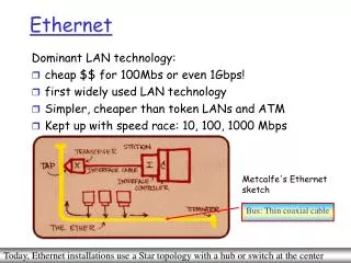
Ethernet. Dominant LAN technology: cheap $$ for 100Mbs or even 1Gbps! first widely used LAN technology Simpler, cheaper than token LANs and ATM Kept up with speed race: 10, 100, 1000 Mbps. Metcalfe's Ethernet sketch. Bus: Thin coaxial cable.

E N D
Ethernet Dominant LAN technology: • cheap $$ for 100Mbs or even 1Gbps! • first widely used LAN technology • Simpler, cheaper than token LANs and ATM • Kept up with speed race: 10, 100, 1000 Mbps Metcalfe's Ethernet sketch Bus: Thin coaxial cable Today, Ethernet installations use a Star topology with a hub or switch at the center
Star topology • Bus topology popular through mid 90s • Now star topology prevails • Connection choices: hub or switch (more later) hub or switch
Ethernet Frame Structure Sending adapter encapsulates IP datagram (or other network layer protocol packet) in Ethernet frame Preamble: • 7 bytes with pattern 10101010 followed by one byte with pattern 10101011 • used to synchronize receiver, sender clock rates If there’s a match, pass frame’s data field to Network Layer; otherwise, discard [46, 1500 bytes] If over, fragment; else if less than 46, have it stuffed
Ethernet Frame Structure (more) • Addresses: 6 bytes, frame is received by all adapters on a LAN and dropped if address does not match • Type: indicates the higher layer protocol, mostly IP but others may be supported such as Novell IPX and AppleTalk) • CRC: checked at receiver, if error is detected, the frame is simply dropped
Unreliable, connectionless service • Connectionless: No handshaking between sending and receiving adapter. • Unreliable: receiving adapter doesn’t send acks or nacks to sending adapter • stream of datagrams passed to network layer can have gaps • gaps will be filled if app is using TCP • otherwise, app will see the gaps
No slots adapter doesn’t transmit if it senses that some other adapter is transmitting, that is, carrier sense transmitting adapter aborts when it senses that another adapter is transmitting, that is, collision detection Before attempting a retransmission, adapter waits a random time, that is, random access Ethernet uses CSMA/CD
1. Adaptor receives datagram from net layer & creates frame 2. If adapter senses channel idle, it starts to transmit frame. If it senses channel busy, waits until channel idle and then transmits 3. If adapter transmits entire frame without detecting another transmission, the adapter is done with frame ! 4. If adapter detects another transmission while transmitting, aborts and sends jam signal 5. After aborting, adapter enters exponential backoff: after the mth collision, adapter chooses a K at random from {0,1,2,…,2m-1}. Adapter waits K·512 bit times and returns to Step 2 Ethernet CSMA/CD algorithm =min(10, num of collisions) No signal energy in channel for 96 bit times
Jam Signal: make sure all other transmitters are aware of collision; 48 bits Bit time: .1 microsec for 10 Mbps Ethernet ;for K=1023, wait time is about 50 msec Exponential Backoff: Goal: adapt retransmission attempts to estimated current load heavy load: random wait will be longer first collision: choose K from {0,1}; delay is K· 512 bit transmission times after second collision: choose K from {0,1,2,3}… after ten collisions, choose K from {0,1,2,3,4,…,1023} Ethernet’s CSMA/CD (more)
CSMA/CD efficiency Long-run fraction of time during which frames are being transmitted on the channel without collisions when there is a large number of active nodes, with each node having a large number of frames to send. • Tprop = max prop between 2 nodes in LAN • ttrans = time to transmit max-size frame • Efficiency goes to 1 as tprop goes to 0 • Goes to 1 as ttrans goes to infinity • Much better than ALOHA, but still decentralized, simple, and cheap
Ethernet Technologies: 10Base2 (1990s) • 10: 10Mbps; 2: under 200 meters max cable length • Max distance bet. 2 nodes without a repeater in between • thin coaxial cable in a bus topology (broadcast technology) • repeaters used to connect up to multiple segments • repeater repeats bits it hears on one interface to its other interfaces: physical layer device only!
10BaseT and 100BaseT (802.3 LAN) Standardized by IEEE 802.3 • 10/100 Mbps rate; latter called ''fast ethernet'' • T stands for Twisted Pair • There is a Hub (broadcast technology) to which nodes are connected by 2 pairs of twisted pair (Category 5 with RJ-45 connector), thus ''star topology'' • CSMA/CD not implemented at hub; adapter sense the channel and detect collision during transmission Transmit, receive Adapter has a point-to-point connection to the hub
10BaseT and 100BaseT (more) • Max distance from node to Hub is 100 meters Management Features • Hub can internally disconnect jabbering adapter • Hub can gather monitoring information, statistics for display to LAN administrators • Bandwidth usage, collision rates, average frame sizes, etc. – for network debugging, correction, future planning
Gbit Ethernet (IEEE 802.3z) • use standard Ethernet frame format • allows for point-to-point links and shared broadcast channels • in shared mode, CSMA/CD is used; short distances between nodes to be efficient • uses Star topology with hub, called here ''Buffered Distributor'‘ or switch at center • Full-Duplex at 1 Gbps for point-to-point links • Serves as a backbone for interconnecting multiple 10Mbps, 100 Mbps Ethernet LANs 10Gbit (802.3ae) extends Ethernet technology to point-to-point WAN links
Interconnecting LANs Q: Why not just one big LAN? • Limited amount of supportable traffic: on single LAN, all stations must share bandwidth • limited length: 802.3 specifies maximum cable length • Large ''collision domain'' (can collide with many stations) • limited number of stations: 802.5 have token passing delays at each station
Definition of Terms Hubs • Physical Layer devices: essentially repeaters operating at bit levels: repeat received bits on one interface to all other interfaces • Hubs can be arranged in a hierarchy (or multi-tier design), with backbone hub at its top
Hubs (more) • Each connected LAN referred to as LAN segment • Hubs do not isolate collision domains: node may collide with any node residing at any segment in LAN • Hub Advantages: • simple, inexpensive device • Allows Inter-LAN segment communication • As a multi-tier, it provides graceful degradation: portions of the LAN continue to operate if one hub malfunctions • extends maximum distance between node pairs (100m per Hub)
Hub limitations • single collision domain results in no increase in max throughput • multi-tier throughput same as single segment throughput • individual LAN restrictions pose limits on number of nodes in same collision domain and on total allowed geographical coverage • cannot connect different Ethernet types (e.g., 10BaseT and 100baseT) • Constraints: • Total number of hosts in a multi-tier LAN • Geographical reach of multi-tier LAN
Bridges • Link Layer devices: operate on Ethernet frames, examining frame header and selectively forwarding frame based on its destination • Bridge isolates collision domains since it buffers frames and uses LAN destination addresses • When a frame is to be forwarded on a LAN segment, a bridge uses CSMA/CD to access segment and transmit
Bridges (more) • Bridge advantages: • Isolates collision domains resulting in higher total max throughput, and does not limit the number of nodes nor geographical coverage • Can connect different type Ethernet since it is a store and forward device • Transparent: no need for any change to host’s LAN adapter configuration when connecting to a bridge
Bridges: frame filtering, forwarding • bridges filter packets • same-LAN -segment frames are not forwarded onto other LAN segments • forwarding: • how to know which LAN segment on which to forward frame? • looks like a routing problem (more shortly!)
Interconnection Without Backbone • Not recommended for two reasons: - single point of failure at Computer Science hub - all traffic between EE and SE must path over CS segment
Bridge Filtering • bridges learn which hosts can be reached through which interfaces by maintaining a filtering table • when a frame received, the bridge ''learns'' the location of the sender: incoming LAN segment • records sender location in filtering table • filtering table entry: • (Node LAN Address, Bridge Interface, Time Stamp) • stale entries in the Filtering Table are dropped (TTL can be 60 minutes)
Bridge Filtering • filtering procedure: ifdestination is on LAN on which frame was received then drop the frame else{ lookup filtering table if entry found for destination then forward the frame on interface indicated; else flood; /* forward on all but the interface on which the frame arrived*/ }
C sends the frame to the bridge, but the bridge has no info. about D, so it floods both LANs • bridge notes that C is on port 1 • frame ignored on upper LAN • frame received by D Bridge Learning: example Suppose C sends a frame to D and D replies back with a frame to C
D generates a reply to C, sends • bridge sees frame from D • bridge notes that D is on interface 2 • bridge knows C on interface 1, so it selectively forwards the frame out via interface 1 Bridge Learning: example
Disabled Bridges Spanning Tree • for increased reliability, it is desirable to have redundant, alternate paths from source to dest • with multiple simultaneous paths, cycles result - bridges may multiply and forward frame forever • solution: organize bridges in a spanning tree by disabling subset of interfaces
Bridges vs. Routers • both store-and-forward devices • routers: network layer devices (examine network layer headers) • bridges are Link Layer devices • routers maintain routing tables, implement routing algorithms • bridges maintain filtering tables, implement filtering, learning and spanning tree algorithms
Routers vs. Bridges Bridges + and - + Bridge operation is simpler requiring less processing bandwidth - Topologies are restricted with bridges: a spanning tree must be built to avoid cycles - Bridges do not offer protection from broadcast storms (endless broadcasting by a host will be forwarded by a bridge)
Routers vs. Bridges Routers + and - + arbitrary topologies can be supported, cycling is limited by TTL counters (and good routing protocols) + provide firewall protection against broadcast storms - require IP address configuration (not plug and play) - require higher processing bandwidth • bridges do well in small (few hundred hosts) while routers used in large networks (thousands of hosts)
Interconnection Devices COMPARISON OF FEATURES
Ethernet Switches • Full-fledged packet switch • layer 2 (frame) forwarding, filtering using LAN addresses • Each LAN segment – in an isolated collision domain • Switching: A-to-B and A'-to-B' simultaneously, no collisions • large number of interfaces • often: individual hosts, star-connected into switch • Ethernet, but no collisions! Provides direct upstream & downstream connections; collision detection & carrier sensing are not needed
Ethernet Switches • Operate in full-duplex • cut-through switching: frame forwarded from input to output port without awaiting for assembly of entire frame • slight reduction in latency • combinations of shared/dedicated, 10/100/1000 Mbps interfaces For as long as the packet’s destination is known, switch transmits packet (with carrier sensing)
Ethernet Switches (more) Institutional Network using a combination of hubs, Ethernet switches, router Dedicated Shared
Extra Topics Wireless Networking is not going to be included in the Finals.
Basic Service Set (BSS) (a.k.a. cell) contains: • wireless hosts • access point (AP): base station • BSSs combine to form distribution system (DS) IEEE 802.11 Wireless LAN • wireless LANs: untethered (often mobile) networking • IEEE 802.11 standard: • MAC protocol • unlicensed frequency spectrum: 900Mhz, 2.4Ghz
Elements of a Wireless Network Wireless host Network Infrastructure Wireless Access Point Coverage area
Elements of a Wireless Network Wireless Hosts • end-system devices that run applications • e.g. laptop, palmtop, PDA, phone, desktop computer Wireless Links • connects hosts to base station or another wireless host • e.g. 802.11a, 802.11g, 802.11b, UMTS/WCDMA, GSM, etc. Base Station • sends/receives packets to and from a wireless host associated with base station; coordinates multiple transmissions of hosts • e.g. cell towers (cellular networks), Access Points (802.11 wireless LANs) Network Infrastructure Network Infrastructure • larger network with which a wireless host connects to
From wired to wireless Replacing a simple wired home network with a wireless 802.11 net • Wireless NIC replaces wired Ethernet card at Hosts • Access Point replaces Ethernet switch • Virtually no changes needed at the network layer or above • Main focus of system changes: link-layer
Wireless Design Considerations Problem: Decreasing signal strength • radio signal passing through wall • signal in free space - disperses Results in decreased Signal strength (or even path loss) • electromagnetic radiation attenuates as it passes through matter
Wireless Design Considerations Problem: Interference from other sources • 2.4 GHz wireless phones • 802.11b wireless LAN Same frequency! • microwave • nearby motor Electromagnetic noise • radio sources transmitting in the same frequency band interferes with each other
Wireless Design Considerations Problem: Multipath Propagation • Portions of electromagnetic wave reflect off objects and the ground – results in blurring of received signal at receiver
Wireless Design Considerations Problem: Multipath Propagation It is also sometimes possible to mount the antenna so that the mounting structure screens it from the reflections but not from the wanted signal. Changing the antenna height can effectively reduce or eliminate the multipath signals by dispersing the signals away from the receiving antenna
Wireless Links • High and time-varying bit error rates will be more common • 802.11 employs CRC error detection codes • 802.11 uses link-level ARQ protocols that retransmit corrupted frames • Broadcasting problem: Undetectable collisions • hidden terminal problem – occurs when physical obstructions in the environment prevent hosts from detecting each other. • hidden terminals: A, C cannot hear each other • obstacles • signal attenuation • collisions at B
Broadcasting problem: Undetectable collisions • Fading of a signal’s strength causes undetectable collisions • goal: avoid collisions at B • CSMA/CA: CSMA with Collision Avoidance • A and C are placed such that their signals are not strong enough to detect each other’s transmissions, yet strong enough to interfere with each other at Host B.
IEEE 802.11 Standards SUMMARY Operating at higher frequency results in shorter transmission distance for a given power level and suffer more from multipath propagation ISM bands in the United States.
IEEE 802.11 Architecture Ad hoc Network • network with no central control and with no connections to the outside world • formed “on the fly” – mobile devices in proximity communicates with each other in the absence of a centralized AP
IEEE 802.11 Architecture Infrastructure Wireless LAN Wireless host Network Infrastructure Wireless Access Point Basic Service Set (BSS)