Download
1 / 31
310 likes | 445 Views
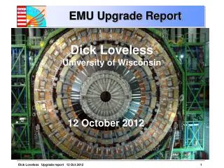
EMU installation. Giorgio Apollinari Quarterly Lehman Review 14 th December, 2002. Scope of EMU Installation. Chambers: 396 cathode-strip chambers Typical size: 3.3 x 1.5 m 2 Typical mass: ~400 kg Services: Gas (Ar-CO 2 -CF 4 ) & Water cooling High voltage Power Peripheral Crates

E N D
EMU installation • Giorgio Apollinari • Quarterly Lehman Review • 14th December, 2002
Scope of EMU Installation • Chambers: • 396 cathode-strip chambers • Typical size: 3.3 x 1.5 m2 • Typical mass: ~400 kg • Services: • Gas (Ar-CO2-CF4) & Water cooling • High voltage • Power • Peripheral Crates • Testing: • Portable DAQ crate (individual chambers) • Slice tests (sectors of chambers)
Chamber Installation • Mount Chambers • On the vertical face of each disk using posts • At the specified angular rotation • Overlap chambers on most faces • Chamber location requirement roughly few mm from the trigger primitives (knowledge of location roughly 100-200mm) • NO Adjustment of Chambers • Kawasaki can drill more accurately in the disk face than we can measure during installation • Drill M12 dowel holes in iron disk sectors • Photogrammetry measurements show 0.2mm accuracy after assembly at CERN
Typical Mount Post
Installation Fixture • Installation fixture built and demonstrated at PSL/FNAL/CERN • Install/remove random CSC chamber in surface hall SX5 or underground hall UX5 • Motorized adjustment of center of gravity • Rotating frame (fits all size CSC chambers) • Load test at 150% • CERN approval process • Safety calculations accepted by TIS • Compliance with Euro Directive 98/37/CE • Instruction manual available • Registered and approved for use by CERN Oct ‘01
Installation Fixture (1) Demonstration at FNAL Installing at CERN
Installation Fixture (2) Just after Installation Prototype CSC on YE2
Installation in SX5 • Begin with YE-2, then YE+2 (no RPC!) • Endcap walkways (CMS-Common Project) done • CSC mounting posts (EMU) done • Endcap muon shielding (before posts) (CMS-Infrastructure) • Endcap connections (CMS-C&I) • Gas bulkheads done • Piping to bulkhead (by MITEX, 80% on EMU) (CERN - EMU pays) • Service boxes - HV, LV (could be added later) (EMU) • Install back chambers for stations ME2, ME3 (EMU) feb ’03 • Install cable trays (EMU) • Connect installed CSCs with gas, water, cables (EMU) • Install front ME2/1 and ME3/1 chambers (20-degree) (EMU) • Connect (gas, water, cables) ME2/1 and ME3/1 (EMU) • Install ME2/2 and ME3/2 chambers (EMU) • Connect all remaining gas, water, cables (EMU)
YE1 Problem • Long term (up to FY ’05) Installation of ME1/2, ME1/3 CSCs • Following cables/services Installation for EE/ES/HE • Following Installation of RE1/2, RE1/3 (RPCs) • Prodding CERN through YE1 EDR • Continuing task
Installation Sequence in SX5 (1) Add corner posts and CSC mounts
Installation Sequence in SX5 (2) Water manifold installed and 1st cable tray Back CSCs installed and cabled, HV and LV installed
Installation Sequence in SX5 (3) 20-degree CSCs installed and cabled All CSCs installed and cabled, VME crates in place
Alignment installation • Scope • 3 straight line monitors (SLM) per station • 1 out of 6 chambers (ME23/2) have alignment mounts • 6 link plates per station • Procedure • Glue island plates before installing chamber • Attach mounting brackets and photogrammetry targets after cabling is complete (and tested) • Complete SLMs and test • Photogrammetry survey and compare with SLM results
Status of tasks • Mounting Posts (EMU) • All YE2 posts finished & shipped to CERN • YE1 posts machined, will be welded when RPC is approved (EDR) • Muon Chambers • 127 chambers finished at Fermilab (out of 148) • 36 chambers finished at PNPI (out of 114) • 72 chambers finished at IHEP (out of 148) • 45 chambers have electronics assembled, tested & shipped to CERN from USA • Skew-clear cables (EMU) • YE2 cables in production, some deliveries to CERN • YE1 layout and length definitions complete, expect approval for production in Sept.
Status of tasks • Gas System (CERN & EMU) • Contract with Mitek (Polish company) • Installation begins in Feb ‘03 • All ME gas bulkheads produced & shipped to CERN • ASK DICK GAS PIPING SLIDES • Cooling (EMU) • All hoses and fittings (valves, couplings, flow restrictors, etc.) purchased and rec’d • YE2 manifolds under contract - will be finished in 4 months • YE1 manifold waiting for info from EE, HE, etc. (completely designed, except location of laterals (feed to individual chambers) ).
Cabling & Commissioning • Skewclear Cables (data) • Length calculated in 3D CAD program, cables made up with specific lengths and labeled with type and length • Cables mounted one at a time, starting at the VME crate, following along the walkways and the cable trays, then connecting to the chamber (leaving the loop of extra cable in the cable tray area) • Labels added specifying locations at both ends at installation time • HV, power cables • Start at chamber and run to outer periphery of disk • Connect to HV and LV as possible
EMU Peripheral VME rack Skew Clear Cables
Installation Manpower • People located at CERN • Peter Levchenko -- physicist supervising the receiving, testing, cabling, and commissioning • 6-8 Techs (PNPI, IHEP, UCLA, UC Davis, ….) • ISR receiving site: • Receive chambers, perform minimal tests to be sure shipping has not caused any damage • SX5 installation site • Team of 3 experts from Wisconsin available during installation windows -- mechanical installation (chambers, gas laterals, cooling piping, etc.) • Cabling - 3-5 techs installing the cables
General explanations • Diamonds: chambers arrive at ISR. Color coding is for chambers from US, PNPI, and IHEP (open diamonds for IHEP mean that these chambers can come much later—as late as the first full diamond) • For the first shipments, there is one-month lag is built-in between arrival of chambers to ISR and beginning of installation at SX5. This is for pre-testing of chambers at ISR (chamber integrity, noise, connectivity). Alignment plates (each 6th chamber) are glued at the same time. • Red bars: SX5 installation windows open for EMU as of V33 • Blue bars: Actual chamber installation/commissioning bursts at SX5 (stations and number of chambers are in the titles). These bars should be within installation windows. Full blue bars indicate the initial pace of 1 chamber per day (including everything). Later, bars become light blue—the pace should shrink by a factor of 2. • Missing pieces: VME and off-chamber electronics installation and commissioning Alignment sensor installation and commissioning • Drop-dead end of all installation/commissioning at SX5 (arrow marks at the end of red bars of installation windows) YE+ December 2004 YE- August 2005
EMU Commissioning • Commissioning: • Commissioning of most of the EMU system will be funded in the US by the M&O Phase (Maintenance & Operation) and take place between CY03 and CY09. • US CMS, IHEP China and PNPI Russia will share responsibilities for the commissioning of the ME2, ME3 and ME1/2-ME1/3 system commissioning. Dubna Russia will be responsible for the commissioning of the ME1/1 system. • The M&O Management team in the US-PNPI-IHEP Collaboration is structured along the lines shown on the side.
EMU Commissioning • Commissioning Structure • CSC Commissioning/Maintenance • FEE Commissioning/Maintenance & Integration • DAQ Interface, Slice Test and On-line Database • DCS Controls • Alignment, Calibration & Off-line Database • EMU Commissioning “Scope of Work”: • Expected Deliverables from Construction phase • Major Commissioning Deliverables • Major Milestones
CSC Commissioning • (Some of the) CSC Commissioning Goals • Maintain and Repair CSCs on Disk • Define Procedures for Gas and Cooling Water operations on installed CSCs • Define Procedures for HV/LV operations and apply HV/LV to CSCs • Portable HV/LV initially. • Test of CSCs mounted on Disks. • Portable DAQ initially (check for signs of life), Slice Test DAQ, • Software for HV/LV Firmware. • Setup CSCs repair procedures. • Maintain Chamber/Cables Databases • Establish and Maintain stock and spare mechanical parts at CERN. • (Some of the) CSC Commissioning Milestones • Minimal Testing of CSCs on disk (Start) 3/1/03 • Portable HV/LV to CSCs on disk 4/1/03 • Final HV to CSCs on disk 6/1/05 • On-line CSCs Monitoring (Programs Available) 6/1/04
FEE Commissioning • (Some of the) FEE Commissioning Goals • Develop power on/off Procedures • Address System integration issues on disk (common noise, gourd loops, etc.) • Most critical part of FEE commissioning • Determine optimal AFEB thresholds, CFEB triggering primitive thresholds and trigger mode • Develop methods to time in electronics and determine optimal timing constants • Benefiting from cosmic m passing through CSCs • Develop various procedures and monitoring systems to monitor and diagnose AFEB, CFEB, ALCT, etc. defining parameters and standards of operations.
M&O Cost Estimate and Funding (1) • Manpower and M&S Cost Estimate and Funding • High-level, Institutional Memory manpower funding (Engineers) allocated explicitly to EMU Institutions • Funding for Foreign Collaborators allocated in agreement with signed MOUs • Signed MOU with PNPI: US M&O to cover for cost of one technician and car at CERN. PNPI will provide 3 additional technicians as contribution to the M&O phase (~300 k$) • Expected base of negotiations: US M&O supporting car at CERN for IHEP Visitors. IHEP to provide 2 technicians as contribution to the M&O phase (~100 k$) • Low-level, technical support manpower funding (technicians, riggers, drafters) concentrated in the hands of the L2 M&O Manager and maintained in two accounts at CERN and FNAL. • M&S funding treated similarly (funds in two accounts at CERN and FNAL under L2 M&O Manager responsibility). • Lower level justification for M&S and technical manpower funding is provided in the M&O Project files. • Funding for several Software Engineers needed during the M&O phase will be maintained at CERN as well to provide uniformity of quality and hiring practices, maybe through the CERN Computing Division.
M&O Cost Estimate and Funding (3) • Total M&O EMU Funding 11.0 M$ • Institutional Manpower 3.4 M$ • FNAL “M&S” 3.2 M$ • CERN “M&S” 4.4 M$
Working Scenario • Possible CY03 Working scenario • Completion of back-CSCs and Cables Installation on YE-2 disk by Mar. ’03 • Water and Gas to CSCs by May-June 03 • Access to EMU Commissioning group (distinct from the EMU Installation group) to CSCs on disk by July-August ’03 • Initial testing will look only for signs-of-life from FEE and CSCs (~1-2days/CSC initially, with probably a rather long learning curve for the first 2-3 CSCs) • Manpower Approach • Maintain Commissioning and Installation crew initially separate • Provide separate set of tools (diagnostic, DAQ systems, etc.) to the two teams • Merge the two teams as Installation work and Parts Handling at ISR winds down • Commissioning team • UCLA FAST Site Personnel M.Ignatenko • Purdue Personnel A.Bujak • PNPI and IHEP Collaborators TBD • Repairs: • (Difficult) CSCs repair contracted to PNPI assembly factory • (Difficult) FEE repairs performed at US Home Institution
Installation/Commissioning in SX5 • Things will not go according to plan • EMU windows will change (possibly with short notice) • RPCs likely to be major delay • Therefore • CSC installation must be flexible -- install chambers as quickly as possible • Most subsystems are late - less demand for facilities (cranes, cherry pickers, etc.) early, install chambers as they become available • Block out 1-2 week periods with crane and cherry-picker control, crew available for trips to CERN on short notice • Commissioning crew resident at CERN
Installation/Commissioning summary • Status: • Installation fixture tested & approved • Most M&S costs already spent or committed • Manpower sufficient for installation & commissioning • Plans: • Install 18 chambers beginning Feb ‘03 (already delayed by 3 months) • We will be ready to start on schedule • Install remaining chambers as quickly as possible • Can make up lost time quickly • Start Minimal CSCs commissioning as soon as access to chambers is allowed