Download
1 / 83
830 likes | 837 Views
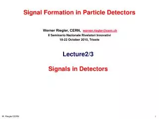
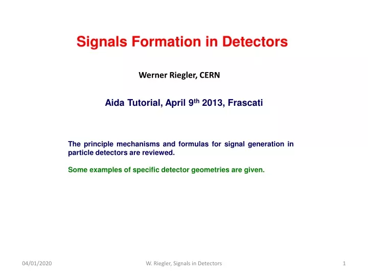
Signals Formation in Detectors. Werner Riegler, CERN. Aida Tutorial, April 9 th 2013, Frascati. The principle mechanisms and formulas for signal generation in particle detectors are reviewed. Some examples of specific detector geometries are given. Signals in Detectors.

E N D
Signals Formation in Detectors Werner Riegler, CERN Aida Tutorial, April 9th 2013, Frascati The principle mechanisms and formulas for signal generation in particle detectors are reviewed. Some examples of specific detector geometries are given. W. Riegler, Signals in Detectors
Signals in Detectors Although the principles and formulas are well known since a long time, there exists considerable confusion about this topic. This is probably due to different vocabulary in different detector traditions and also due to the fact that the signal explanations in many (or most !) textbooks on particle detectors are simply wrong. W. Riegler, Signals in Detectors
Creation of the Signal From a modern detector text book: … It is important to realize that the signals from wire chambers operating in proportional mode are primarily generated by induction due to the moving charges rather than by the collection of these charges on the electrodes … … When a charged […] particle traverses the gap, it ionizes the atoms […]. Because of the presence of an electric field, the electrons and ions created in this process drift to their respective electrodes. The charge collected at these electrodes forms the […] signal, in contrast to gaseous detectors described above, where the signal corresponds to the current induced on the electrodes by the drifting charges (ions). … These statements are completely wrong ! All signals in particle detectors are due to induction by moving charges. Once the charges have arrived at the electrodes the signals are ‘over’. W. Riegler, Signals in Detectors
Signals in Detectors Details (correct) of signal theorems and electronics for signal processing can be found in this book. W. Riegler/CERN
Creation of the Signal • Charged particles leave a trail of ions (and excited atoms) along their path: Electron-Ion pairs in gases and liquids, electron hole pairs in solids. • Photons from de-excitation are usually converted to electrons for detection. • The produced charges can be registered Position measurement Time measurement Tracking Detectors .... • Cloud Chamber: Charges create drops photography. • Bubble Chamber: Charges create bubbles photography. • Emulsion: Charges ‘blacked’ the film. • Spark Chamber: Charges produce a conductive channel that create a discharge photography • Gas and Solid State Detectors: Moving Charges (electric fields) induce electronic signals on metallic electrons that can be read by dedicated electronics. • In solid state detectors the charge created by the incoming particle is sufficient (not exactly correct, in Avalanche Photo Diodes one produces avalanches in a solid state detector) • In gas detectors (Wire Chambers, GEMs, MICROMEGAS) the charges are internally multiplied in order to provide a measurable signal. W. Riegler, Signals in Detectors
Cloud Chamber, C.T.R. Wilson 1910 Charges act as condensation nuclei in supersaturated water vapor Alphas, Philipp 1926 Positron discovery, Carl Andersen 1933 V- particles, Rochester and Wilson, 1940ies W. Riegler, Signals in Detectors
Nuclear Emulsion, M. Blau 1930ies Charges initiate a chemical reaction that blackens the emulsion (film) C. Powell, Discovery of muon and pion, 1947 Kaon Decay into 3 pions, 1949 Cosmic Ray Composition W. Riegler, Signals in Detectors
Bubble Chamber, D. Glaser 1952 Charges create bubbles in superheated liquid, e.g. propane or Hydrogen (Alvarez) Discovery of the Ω- in 1964 Neutral Currents 1973 Charmed Baryon, 1975 W. Riegler, Signals in Detectors
Spark Chamber, 1960ies Charges create ‘conductive channel’ which initiates a spark in case HV is applied. Discovery of the Muon Neutrino 1960ies W. Riegler, Signals in Detectors
Tip Counter, Geiger 1914 Charges create a discharge of a needle which is at HV with respect to a cylinder. The needle is connected to an electroscope that can detect the produced charge. W. Riegler, Signals in Detectors
Electric Registration of Geiger Müller Tube Signals Charges create a discharge in a cylinder with a thin wire set to HV. The charge is measured with a electronics circuit consisting of tubes electronic signal. W. Bothe, 1928 B. Rossi, 1932 Cosmic Ray Telescope 1930ies W. Riegler, Signals in Detectors
Ionization Chambers, Wire Chambers, Solid State Detectors The movement of charges in electric fields induces signals on readout electrodes (No discharge, there is no charge flowing from cathode to Anode) W. Riegler, Signals in Detectors
The Principle of Signal Induction on Metal Electrodes by Moving Charges W. Riegler, Signals in Detectors
Induced Charges A point charge q at a distance z0 above a grounded metal plate ‘induces’ a surface charge. + q z0 - - - - - - - - - W. Riegler, Signals in Detectors
Electrostatics, Things we Know Poisson Equation: Gauss Law: Metal Surface: Electric Field is perpendicular to the surface. Charges are only on the surface. Surface Charge Density σ and electric E field on the surface are related by E E A σ A σ E=0 Perfect Conductor W. Riegler, Signals in Detectors
Induced Charges In order to find the charge induced on an electrode we therefore have to Solve the Poisson equation with boundary condition that φ=0 on the conductor surface. Calculate the electric field E on the surface of the conductor Integrate e0E over the electrode surface. + q z0 - - - - - - - - - W. Riegler, Signals in Detectors
Induced Charges The solution for the field of a point charge in front of a metal plate is equal to the solution of the charge together with a (negative) mirror charge at z=-z0. q q + + E E = z0 z0 - - - - - - - - - z0 - The field on the electrode surface (z=0) is therefore W. Riegler, Signals in Detectors
Induced Charges We therefore find a surface charge density of And therefore a total induced charge of + q z0 - - - - - - - - - W. Riegler, Signals in Detectors
Induced Charges The total charge induced by a point charge q on an infinitely large grounded metal plate is equal to –q, independent of the distance of the charge from the plate. The surface charge distribution is however depending on the distance z0 of the charge q. q + z0 -q - - - - - - - - - W. Riegler, Signals in Detectors
Induced Charges Moving the point charge closer to the metal plate, the surface charge distribution becomes more peaked, the total induced charge is however always equal to –q. q q -q -q I=0 W. Riegler, Signals in Detectors
Signal Induction by Moving Charges The charge induced on the individual strips is now depending on the position z0 of the charge. If the charge is moving there are currents flowing between the strips and ground. The movement of the charge induces a current. If we segment the grounded metal plate and if we ground the individual strips, the surface charge density doesn’t change with respect to the continuous metal plate. q V -q -q I1(t) I2(t) I3(t) I4(t) W. Riegler, Signals in Detectors
Formulation of the Problem In a real particle detector, the electrodes (wires, cathode strips, silicon strips, plate electrodes …) are not grounded but they are connected to readout electronics and interconnected by other discrete elements. We want to answer the question: What are the voltages induced on metal electrodes by a charge q moving along a trajectory x(t), in case these metal electrodes are connected by arbitrary linear impedance components ? W. Riegler, Signals in Detectors
Formulation of the Problem We will divide the problem into two parts: We first calculate the currents induced on grounded electrodes. A theorem, easy to prove, states that we then have to place these currents as ideal current sources on a circuit containing the discrete components and the mutual electrode capacitances + = The second step is typically performed by using an analog circuit simulation program. We will first focus on the induced currents. W. Riegler, Signals in Detectors
Currents on Grounded Electrodes We can imagine this case by reading the signal with an ideal current amplifier of zero input impedance = V2(t)= -R I1(t) W. Riegler, Signals in Detectors
Parallel Plate Chamber Plate 2 q2 D q [5] z0 q1 Plate 1 W. Riegler, Signals in Detectors
Parallel Plate Chamber Plate 2 q2 z0 D q q1 Plate 1 W. Riegler, Signals in Detectors
Parallel Plate Chamber I2(t) Plate 2 q2 z0(t) I1(t) D q q1 Plate 1 W. Riegler, Signals in Detectors
Parallel Plate Chamber I2(t) Plate 2 q2 I1(t) D q z0 q1 The sum of all induced charges is equal to the moving charge at any time. The sum of the induced currents is zero at any time. The field calculation is complicated, the formula for the induced signal is however very simple – there might be an easier way to calculate the signals ? Ramo-Shockley theorem ! Plate 1 W. Riegler, Signals in Detectors
Signal Polarity Definition -q -q +q + + - + +q - + + + - + - + - - + - - + - - I(t) I(t) Positive Signal Negative Signal The definition of I=-dQ/dt states that the positive current is pointing away from the electrode. The signal is positive if: Positive charge is moving from electrode to ground or Negative charge is moving from ground to the electrode The signal is negative if: Negative charge is moving from electrode to ground or Positive charge is moving from ground to the electrode W. Riegler, Signals in Detectors
Signal Polarity Definition -q -q +q + + - + +q - + + + - + - + - - + - - + - - I(t) I(t) Positive Signal Negative Signal By this we can guess the signal polarities: In a wire chamber, the electrons are moving towards the wire, which means that they attract positive charges that are moving from ground to the electrode. The signal of a wire that collects electrons is therefore negative. W. Riegler, Signals in Detectors
Sum of Induced Charges and Currents A E V q The surface A must be oriented towards the outside of the volume V. V A=A1+A2+A3 q A2 A1 A3 W. Riegler, Signals in Detectors
Sum of Induced Charges and Currents V Q2 Q1 q Q3 In case the surfaces are metal electrodes we know that And we therefore have In case there is one electrode enclosing all the others, the sum of all induced charges is always equal to the point charge. The sum of all induced currents is therefore zero at any time ! W. Riegler, Signals in Detectors
Charged Electrodes Setting the three electrodes to potentials V1, V2, V3 results in charges Q1, Q2, Q3. In order to find them we have to solve the Laplace equation with boundary condition And the calculate W. Riegler, Signals in Detectors
Green’s Second Theorem Gauss Law which is valid for Vector Field and Volume V surrounded by the Surface A: By setting and setting and subtracting the two expressions we get Green’s second theorem: W. Riegler, Signals in Detectors
Green’s Theorem, Reciprocity Reciprocity Theorem It related two electrostatic states, i.e. two sets of voltages and charges W. Riegler, Signals in Detectors
Electrostatics, Capacitance Matrix From the reciprocity theorem it follows that the voltages of the electrodes and the charges on the electrodes are related by a matrix The matrix cnm is called the capacitance matrix with the important properties The capacitance matrix elements are not to be confused with the electrode capacitances of the equivalent circuit. They are related by W. Riegler, Signals in Detectors
Induced Charge We assume three grounded electrodes and a point charge in between. We want to know the charges induced on the grounded electrodes. We assume the point charge to be an very small metal electrode with charge q, so we have a system of 4 electrodes with V1=0, V2=0, V3=0, Q0=q. We can now assume another set of voltages and charges where we remove the charge from electrode zero, we put electrode 1 to voltage Vw and keep electrodes 2 and 3 grounded. Using the reciprocity theorem we get W. Riegler, Signals in Detectors
Induced Charge The voltage V0 is the voltage of the small uncharged electrode for the second electrostatic state, and because a small uncharged electrode is equal to having no electrode, V0 is the voltage at the place x of the point charge in case the charge is removed, electrode 1 is put to voltage Vw and the other electrodes are grounded. We call the potential ψ(x) the weighting potential of electrode 1. W. Riegler, Signals in Detectors
Induced Charge The charge induced by a point charge q at position x on a grounded electrode can be calculated the following way: One removes the point charge, puts the electrode in question to potential Vw while keeping the other electrodes grounded. This defines the potential ‘weighting potential’ψ(x) from which the induced charge can be calculated by the above formula. W. Riegler, Signals in Detectors
Induced Current, Ramo Shockley Theorem In case the charge is moving along a trajectory x(t), the time dependent induced charge is And the induced current is W. Riegler, Signals in Detectors
Induced Current The current induced on a grounded electrode n by a moving point charge q is given by Where the weighting field En is defined by removing the point charge, setting the electrode in question to potential Vw and keeping the other electrodes grounded. Removing the charge means that we just have to solve the Laplace equation and not the Poisson equation ! W. Riegler, Signals in Detectors
Parallel Plate Chamber I2(t) Plate 2 q2 v q D z0 q1 Plate 1 I1(t) Weighting field E1 of plate 1: Remove charge, set plate1 to Vw and keep plate2 grounded Weighting field E2 of plate 2: Remove charge, set plate2 to Vw and keep plate1 grounded So we have the induced currents W. Riegler, Signals in Detectors
Arguing with Energy ? Not a good Idea ! V0 dZ E=V0/D q D This argument gives the correct result, it is however only correct for a 2 electrode system because there the weighting field and the real field are equal. In addition the argument is very misleading. W. Riegler, Signals in Detectors
Arguing with Energy ? Not a good Idea ! I2(t) dz q D I1(t) An induced current signal has nothing to do with Energy. In a gas detector the electrons are moving at constant speed in a constant electric field, so the energy gained by the electron in the electric field is lost into collisions with the gas, i.e. heating of the gas. In absence of an electric field, the charge can be moved across the gap without using any force and currents are flowing. The electric signals are due to induction ! W. Riegler, Signals in Detectors
Total Induced Charge If a charge is moving from point x0 to point x1, the induced charge is If a pair of charges +q and -q is produced at point x0 and q moves to x1 while –q moves to x2 , the charge induced on electrode n is given by If the charge q moves to electrode n while the charge –q moves to another electrode, the total induced charge on electrode n is q, because the ψn is equal to Vw on electrode n and equal to zero on all other electrodes. In case both charges go to different electrodes the total induced charge is zero. After ALL charges have arrived at the electrodes, the total induced charge on a given electrode is equal to the charge that has ARRIVED at this electrode. Current signals on electrodes that don’t receive a charge are therefore strictly bipolar. W. Riegler, Signals in Detectors
Induced Charge, ‘Collected’ Charge The fact that the total induced charge on an electrode, once ALL charges have arrived at the electrodes, is equal to the actual charge that has ARRIVED at the electrode, leads to very different ‘vocabulary for detectors in different detectors. In wire chambers the ions take hundreds of microseconds to arrive at the cathodes. Because the electronics ‘integration time’ is typically much shorter than this time, the reality that the signal is ‘induced’ is very well known for wire chambers, and the signal shape is dominated by the movement of the ions. The longer the amplifier integration time, the more charge is integrated, which is sometimes called ‘collected’ , but it has nothing to do with collecting charge from the detector volume … In Silicon Detectors, the electrons and holes take only a few ns to arrive at their electrodes, so e.g. for typical ‘integration times’ of amplifiers of 25ns, the shape is dominated by the amplifier response. The peak of the amplifier output is the proportional to the primary charge, and all the charge is ‘collected’ Still, the signal is not due to charges entering the amplifier from the detector, it is due to induction by the moving charge. Once the charge has actually arrived at the electrode, the signal is over ! W. Riegler, Signals in Detectors
Why not collected Charge ? Imagine an avalanche in a drift tube, caused by a single electron. Let’s assume that the gas gain is 104. We read out the wire signal with an ideal integrator The 104 electrons arrive at the wire within <1ns, so the integrator should instantly see the full charge of -104 e0 electrons ? No ! The ions close to the wire induce the opposite charge on the wire, so in the very beginning there is zero charge on the integrator and only once the Ions have moved away from the wire the integrator measures the full -104 e0 b W. Riegler, Signals in Detectors
Signal Calclulation in 3 Steps What are the signals induced by a moving charge on electrodes that are connected with arbitrary linear impedance elements ? 1) Calculate the particle trajectory in the ‘real’ electric field. 2) Remove all the impedance elements, connect the electrodes to ground and calculate the currents induced by the moving charge on the grounded electrodes. The current induced on a grounded electrode by a charge q moving along a trajectory x(t) is calculated the following way (Ramo Theorem): One removes the charge q from the setup, puts the electrode to voltage V0 while keeping all other electrodes grounded. This results in an electric field En(x), the Weighting Field, in the volume between the electrodes, from which the current is calculated by 3) These currents are then placed as ideal current sources on a circuit where the electrodes are ‘shrunk’ to simple nodes and the mutual electrode capacitances are added between the nodes. These capacitances are calculated from the weighting fields by W. Riegler, Signals in Detectors
General Signal Theorems The following relations hold for the induced currents: 1) The charge induced on an electrode in case a charge q has moved from a point x0 to a point x1 is and is independent on the actual path. 2) Once ALL charges have arrived at the electrodes, the total induced charge on the electrodes is equal to the charge that has ARRIVED at this electrode. 3) In case there is one electrode enclosing all the others, the sum of all induced currents is zero at any time. W. Riegler, Signals in Detectors
Signals in a Parallel Plate Geometry I2 E.g.: Electron-ion pair in gas or Electron-ion pair in a liquid or Electron-hole pair in a solid Z=D z E q,vI Z=z0 -q, ve Z=0 E1=V0/D E2=-V0/D I1= -(-q)/V0*(V0/D)*ve- q/V0 (V0/D) (-vI) = q/D*ve+q/D*vI I2=-I1 I1 I1(t) q TI t Te Qtot1= I1dt = q/D*ve Te + q/D*vI*TI = q/D*ve*(D-z0)/ve + q/D*vI*z0/vI = q(D-z0)/D + qz0/D = qe+qI=q Q1(t) TI t Te The total induced charge on a specific electrode, once all the charges have arrived at the electrodes, is equal to the charge that has arrived at this specific electrode. W. Riegler, Signals in Detectors