Download
1 / 24
240 likes | 383 Views
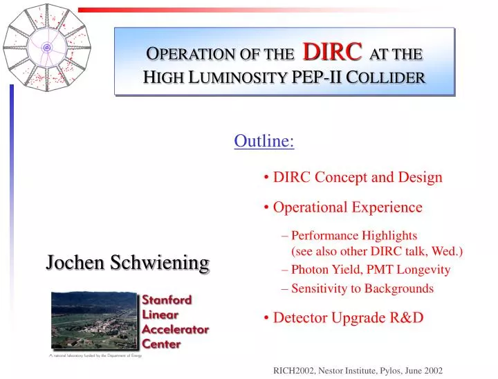
O PERATION OF THE DIRC AT THE H IGH L UMINOSITY PEP-II C OLLIDER. Outline: • DIRC Concept and Design • Operational Experience – Performance Highlights (see also other DIRC talk, Wed.) – Photon Yield, PMT Longevity – Sensitivity to Backgrounds • Detector Upgrade R&D.

E N D
OPERATION OF THE DIRC AT THE HIGH LUMINOSITY PEP-IICOLLIDER • Outline: • • DIRC Concept and Design • • Operational Experience • – Performance Highlights (see also other DIRC talk, Wed.) • – Photon Yield, PMT Longevity • – Sensitivity to Backgrounds • • Detector Upgrade R&D Jochen Schwiening RICH2002, Nestor Institute, Pylos, June 2002
BABAR-DIRC COLLABORATION Novel RICH detector used for the first time in BABAR DIRC combines with dE/dx from drift chamber and vertex detector (mostly in the 1/b2 region) ashadronic particle identification system for BABAR. The BABAR-DIRC Collaboration I.Adam,a R.Aleksan,b D.Aston,a D. Bernard,e G.Bonneaud,e P.Bourgeois,b F. Brochard,e D.N.Brown,f J.Chauveau,c J.Cohen-Tanugi,c M.Convery,a S.Emery,b S.Ferrag,e A.Gaidot,b T.Haas,a T.Hadig,a G.Hamel de Monchenault,b C.Hast,d A.Höcker,d R.W.Kadel,f J.Kadyk,f M. Krishnamurthy,h H. Lacker,c G.W.London,b A.Lu,g A.-M.Lutz,d G.Mancinelli,i B.Mayer,b B.T.Meadows,i Ll.M.Mir,fD.Muller,a J.Ocariz,c S.Plaszczynski,d M.Pripstein,f B.N.Ratcliff,a L.Roos,c M.-H.Schune,d J.Schwiening,a V.Shelkov,f M.D.Sokoloff,i S.Spanier,a J.Stark,cA.V.Telnov,f Ch.Thiebaux,e G.Vasileiadis,e G.Vasseur,b J.Va'vra,a M.Verderi,eW.A.Wenzel,f R.J.Wilson,h G.Wormser,d Ch.Yéche,b S.Yellin,g M.Zito.b a Stanford Linear Accelerator Center b CEA-Saclay, c LPNHE des Universités Paris 6 et Paris 7 d LAL, Universite Paris Sud e Ecole Polytechnique, LPNHE f Lawrence Berkeley National Laboratory g University of California, Santa Barbara h Colorado State University i University of Cincinnati
DIRC PRINCIPLE I • A charged particle traversing a radiator with refractive index n withb = v/c> 1/nemits Cherenkov photons on cone with half opening angle cos qc = 1/nb. • If n>2 some photons are always totally internally reflected for b1 tracks. • Radiator and light guide: Long, rectangular Synthetic Fused Silica (“Quartz”) bars (Spectrosil: average <n(l)> 1.473, radiation hard, homogenous, low chromatic dispersion;144 bars: 4901.73.5 cm3, polished to surface roughness <5Å (rms); square to better than 0.3 mrad.) • Square radiator bar magnitude of qc preserved during internal reflections.Typical DIRC photon:l 400 nm, ~ 200 bounces, ~ 10-60 ns propagation time, ~ 5 m path in quartz.
DIRC PRINCIPLE II < ~ • Only one end of bar instrumented; mirror attached to other (forward) end. • Spectrosil wedge glued to readout end reduces required number of PMTs by ~ factor 2 and improves exit angle efficiency for large angle photons . • Photons exit from wedge into expansion region (filled with 6m3 pure, de-ionized water).(<nwater (l)> 1.346, Standoff distance 120 cm, outside main magnetic field; shielding: B 1 Gauss) • Pinhole imaging on PMT array(bar dimension small compared to standoff distance).(10,752 traditional PMTs ETL 9125, immersed in water, surrounded by hexagonal “light-catcher”, transit time spread ~1.5nsec) • DIRC is a 3-D device, measuring: x, y and time of Cherenkov photons. • PMT / radiator bar combination plus track direction and location from tracking define qc, fc,tpropagation of photon.
DIRC RECONSTRUCTION I DIRC “Ring” images: •limited acceptance for total internal reflection, •reflection ambiguities (initial reflectionup/down, left/right, reflection off mirror, wedge up to 16 (qc, fc) ambiguitiesper PMT hit), •toroidal detection surface, Cherenkovring images are distorted: complex,disjoint images Low energy photons from accelerator hit Standoff Box. At current luminosity that causes rates of 80-200 kHz/tube. 80-200 kHz 10,752 PMTs 300 nsec trigger window 500-1300 background hits (~10% occupancy) compared to50-300 Cherenkov photons
DIRC RECONSTRUCTION II Time information provides powerful tool to reject accelerator and event related background. Calculate expected arrival time of Cherenkov photon based on •track TOF • photon propagation in radiator bar and in water Dt: difference between measured and expected arrival time s(Dt) = 1.7 nsec Dt(nsec) 300 nsec trigger window 8 nsec Dt window(~500-1300 background hits/event)(1-2 background hits/sector/event)
DIRC PERFORMANCE HIGHLIGHTS I Single Photon Cherenkov angle resolution:Dqc,g:difference measured qc,g per photon solution and expected track qc (di-muons) s(Dqc,g) = 9.6 mrad Expectation:~9.5 mraddominatedby: 7mrad from PMT/bar size, 5.4mrad from chromatic term, 2-3mrad from bar imperfections. ~10% Background under Dqc,g peak: combinatoric background, track overlap, accelerator background,d electrons in radiator bar, reflections at fused silica/glue interface, ...
DIRC PERFORMANCE HIGHLIGHTS II Number of Cherenkov photons per track (di-muons) vs. polar angle: Resolution of Cherenkov angle fit per track (di-muons): s(Dqc,) = 2.4 mrad Between 20 and 60 signal photons per track. Very useful feature in BABAR environment: higher momentum correlated with larger polar angle values more signal photons, better resolution (~ 1/N ) Track Cherenkov angle resolution is within ~10% of design. Should improve with advances in track- and DIRC-internal alignment. For more on DIRC performance, see DIRC talk in Wednesday session.
DIRC OPERATIONAL EXPERIENCE: ISSUES DIRC is Stable and Robust • BABAR-DIRC Timeline: • November 1998: installed SOB and one bar box, PMTs in water; • April 1999: BABAR moves into beamline, added 4 more bar boxes; • November 1999: all 12 bar boxes installed, start of first physics run. • The two most significant operational issues that have emerged during three+ years of running: • Sensitivity of the DIRC to machine background interacting in the SOB (primarily DAQ issue) • Concerns about PMT longevity due to PMT window degradation.
DIRC OPERATIONAL EXPERIENCE: STABILITY DIRC is Stable and Robust colors indicate sectors • Calibration constants stable: typical rms of T0 per channel ~ 0.1ns (light pulser and data stream). • Monitor humidity of nitrogen return line from bar box: dew points constant at -45... -55C, no leaks after installation. • Water purification system keeps resistivity at 18.5MWcm (input) and 9.5MWcm (return). • Watertransmission in SOB remains stable at 98%/m (442nm, 325nm), 95%/m (266nm). occupancy 2ns mean T0 (ns) sigma T0 (ns) elapsed time (days)
DIRC OPERATIONAL EXPERIENCE: PMT LONGEVITY I frosty • PMT front window corrosion • Discovered after ~ 1 year immersion Oct. 99. • Status Oct. 99: ~ 50 frosty tubes and ~ 2/3 visibly milky. • Only front glass affected, side glass fine. • Studies • - Strongly corroded (frosty) tubes are a bad batch of PMT glass (no zinc). • - Milkiness results from sodium depletion in near surface. • No obvious immediate effect (water provides good coupling) but ... • Might lose PMT efficiency with time. • Might lose vacuum in some of the ~ 50 frosty tubes on 10 year time scale (front window thickness: 1mm). milky electron microscope image
DIRC OPERATIONAL EXPERIENCE: PMT LONGEVITY II • Chemical analysis of return water from standoff box: • measure Sodium and Boron levels; • three measurements since 1999; • levels indicate loss of 2-3mmper year from PMT windows (1mm thick).
DIRC OPERATIONAL EXPERIENCE: PMT LONGEVITY III broken PMT plunger PMT bundlewith light catchers • Concern with mechanical stability of PMTs when front glass gets thinner (Super-K...) • breaking test of PMT bundle at 4m and 8m water column (DIRC max. < 4m); • used sharp plunger to break PMT front glass; • no breaking of neighboring PMTs observed at either depth.
DIRC OPERATIONAL EXPERIENCE: PMT LONGEVITY IV • Most spectacular failure mode of PMTs: • “Christmas Tree” • loss of vacuum in PMT at base; • discharge in PMT creates many photons, emitted via front or clear side glass; • extra photons are detected by neighbors (sometimes scatter through entire SOB); • rates in affected PMT in MHz range, several 100kHz in neighbors; • PMT dies after few hours – days; • HV of affected PMT immediately (automatically) lowered to preserve data quality; • observed rate: 5-6 per year. Rate in one sector Rate in all sectors Christmas Tree PMT
DIRC OPERATIONAL EXPERIENCE: PMT LONGEVITY V After over three years, 82 PMTs out of 10,752 are dead or inefficient 99.2% fully functional
DIRC OPERATIONAL EXPERIENCE: PHOTON YIELD • Concern: stability of photon yield • PMTdirectly immersed in purified water since 1998; • observed front glass corrosion in October 1999; • no direct experience with maintaining high (>0.999) radiator reflection coefficient for 10 years. • Detailed study of photon yield using: • LED pulsercalibration, • PMT aging tests, • comparison of photon yield in real Bhabha and di-muon events separately for every radiator bar (box). photon yield change per year (%) Consistent result: 1-2% photon yield loss per year. very minor impact on PID performance over 10 year lifetime of DIRC. barbox number
DIRC OPERATIONAL EXPERIENCE: BACKGROUNDS I • PEP-II Luminosity and currents are rapidly increasing • 4*1033 /cm2·snow, • expect >5*1033 /cm2·s atthe end of the 2001/2002 run, • 1-2 *1034 /cm2·sin 2004/5; • 1035 - 1036 /cm2·s discussed(“SuperBABAR”). Dt cut very effective in removing accelerator induced background from reconstruction. But high counting rates cause inefficiency of present DIRC TDC: ~5% inefficiency at 250 kHz DIRC TDC inefficiency Input frequency (kHz)
DIRC OPERATIONAL EXPERIENCE: BACKGROUNDS II Monitor background rates: one PMT/sector is read out via scaler, available online, used in slow control (current operational limit 400kHz). Status during early BABAR running: rates of >250kHz causing noticeable TDC deadtimes at 1/3 of design luminosity Spring 2000 maximum scaler rate (kHz) Started to install localized lead brick shielding to block potential background sources. Luminosity (1033/cm2s)
DIRC OPERATIONAL EXPERIENCE: BACKGROUNDS III Summer 2000 - 2000/2001 shutdown: localized lead brick shielding around beampipe and quadrupoles in BABAR local shielding 2000 maximum scaler rate (kHz) Rate vs. Luminosity showed that lead shielding essential in protecting DIRC from few MeV photon accelerator induced background (radiative Bhabhas etc). More uniform, complete shielding and easier access to detector required. Luminosity (1033/cm2s)
DIRC OPERATIONAL EXPERIENCE: BACKGROUNDS IV In January 2001, installed new, more homogenous lead shielding (5-7cm of lead in upper 2/3, 2-3cm in lower 1/3 of shield). integrated shielding 2001 maximum scaler rate (kHz) PMT rates acceptable even above design lumi. Luminosity (1033/cm2s)
DIRC OPERATIONAL EXPERIENCE: BACKGROUNDS V Effect of Shielding on Rate per PMT Example: installation of integrated shielding(after-before, corrected for machine parameters) PMT Rates in Typical Run May 2002 150 0 PMT Rate (kHz) Rate per PMT 20-25kHz lower in area targeted by shielding Rates vary between 50-150kHz.
DIRC OPERATIONAL EXPERIENCE: BACKGROUNDS VI Background model • Special runs with • HER beam only, • LER beam only, • HER+LER w/o collision Typical 1.0 1.7 4.2 (“Design”) (0.75) (2.14) (3.0) Av. Rate per PMT (kHz) = HER (A) * 13 kHz+ LER (A) * 18 kHz + Lumi (1033/s·cm2) * 10 kHz 86 (78) Current shielding configuration “background safe” through 2002. New TDC chips (faster, deeper buffering) to be installed during shutdown Fall 2002: <5% deadtime at 2.5MHz rate.
DIRC UPGRADE R&D • What about DIRC at 1034 and beyond? (timescale ~2004/5) • R&D program for DIRC upgrade has started: • Large water tank isdominant source of background. • Try to design more compact optics but keep radiator bars. • Replace conventional PMT array with pixelated detectors, i.e., • Hamamatsu “flat panel” 8*8 channel multi-anode PMTs, or • Hybrid Photodiodes (HPDs), • ... (see J. Va’vra talk) • Improve qc resolution and time resolution (at 200ps time information becomes competitive with spatial information in determining Cherenkov angle; decrease chromatic smearing) • Cosmic telescope facility under construction at SLAC to test new optics and new photon detector using full scale DIRC barbox.
CONCLUSIONS • The DIRC is a novel type of particle identification system, well matched to asymmetric B-factory environment, capable of -K separation for momenta up to ~ 4 GeV/c. • Three years of experience in PEP-II/BABAR B-factory mode: DIRC very reliable, robust, easy to operate, 99.2% of channels fully functional. • Machine backgrounds up to 200 kHz/PMT at 4·1033/cm2·s no problem for reconstruction; will install new TDC chips during Fall 2002 shutdown (for 1034/cm2·s luminosity). • Front glass corrosion of PMTs in ultra-pure water observed, due to Sodium leaching. Bad batch of PMT glass in ~50 PMTs, breaking tests show no problems. • Photon yield shows small loss at rate of 1-2%/year, no problem for PID performance. • Single photon time and Cherenkov angle resolution and photon yield close to nominal, track Cherenkov angle resolution within 10%of design. • DIRC plays significant role in almost all BABAR physics analyses published to date. • R&D program under way to prepare DIRC for 1034 /cm2·s and beyond.