Download
1 / 22
220 likes | 377 Views
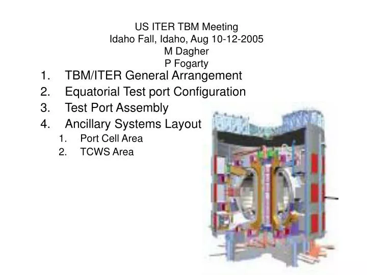
US ITER TBM Meeting Idaho Fall, Idaho, Aug 10-12-2005 M Dagher P Fogarty. TBM/ITER General Arrangement Equatorial Test port Configuration Test Port Assembly Ancillary Systems Layout Port Cell Area TCWS Area. Pipe Shaft Area. Port Cell Area. Bio-shield. Cryostat. Test Port Assy.

E N D
US ITER TBM MeetingIdaho Fall, Idaho, Aug 10-12-2005M DagherP Fogarty TBM/ITER General Arrangement Equatorial Test port Configuration Test Port Assembly Ancillary Systems Layout Port Cell Area TCWS Area
Pipe Shaft Area Port Cell Area Bio-shield Cryostat Test Port Assy
Tokamak Building, East-West Section View Bio-Shield TCWS Area TBM Cooling system Equipment Room Pipe Shaft Area Port Cell Area Cryostat
TCWS Area TBM Cooling system Equipment Room Bio-Shield Shielding Blanket Equatorial Port Cell Area Equatorial Port Assembly
Test Port General Layout Equatorial Level Section Vacuum Vessel Cryostat Bio-Shield Test Blanket Module Pipe Shaft Area Frame Assembly Transporter Port Cell Area Equatorial Level 0.0 VV Port Extension VV Closure Plate
Test Port Configuration VV – Cryostat Duct Cryostat VV Port Extension Bio-Shield TBM Frame Assy Transporter VV Closure Plate Pb-Li Concentric Pipe Port Cell Area
Test Port Configuration Bio-Shield 3.6m 4.8m VV Port Extension Transporter TBM Frame Assy TBM VV Closure Plate
ITER Overall view of Frame Cooling channels at the front of Frame
ITER (B) Removable back-side shield Lip seal Fastening the bolts Design of “removable back-side shield” structure has been developed to accommodate possible different TBM attachments (support structures, electrical connection, cooling pipes and instrumentation).
25 mm gap all around inside frame openings 25 25 413 1710 5 25 504
504 Module Width Plan View Blanket Module Helium OUT Plenums (Top & Bottom Plates, Grid Plates & Dividers) Helium IN Plenum First Wall (Lower Channel) All Helium OUT Helium IN Plenum First Wall (Upper Channel) 68 mm I.D. Pipe Inlet Helium IN Helium IN 5 (typ wall) Back Plates Helium OUT First Wall 68mm I.D. Pipe Inlet 75 Outer Back Plate 65 95 Inner Back Plate 85 413 Module Depth 15 Grid Plate 120 PbLi OUT Helium flow channels for actively cooling The back plates 139.3 (typ 3 places) 15 Divider 7 (channel) 7 (channel) 20 (channel) 80 PbLi - IN 4 (typ wall) 28 First Wall Dimensions in millimeters
Ancillary Systems • Port Cell Area • Primary Coolant Loop Pb-Li – He • Tritium Extraction System • TCWS Area • Primary FW He Coolant Loop • Secondary Coolant Systems
Primary He Coolant Loop TCWS Secondary He Coolant Loop TCWS Test Port Pb-Li Primary Coolant Loop Transporter, Port Cell Area
Pb-Li Primary Coolant Loop Tritium Extraction System Pb-Li Concentric Pipe Pb-Li Pump Expansion Tank Pb-Li Mixing Tank Pb-Li – He Heat Exchanger Pb-Li Dump Tank
He Secondary Coolant Loops Heater Element He-H2O Heat Exchanger Pressure Control Sub-System He Circulator