Download
1 / 115
1.19k likes | 1.56k Views
Local & Metropolitan Area Networks. ACOE3 2 2 Lecture 4 Metropolitan Area Networks. 0. Overview. In this section the following topics will be covered: Internetworking devices Wide Area Networks 2.1 ISDN and Broadband ISDN 2.2 X.25 2.3 Frame Relay 2.4 ATM

E N D
Local & Metropolitan Area Networks ACOE322 Lecture 4 Metropolitan Area Networks
0. Overview • In this section the following topics will be covered: • Internetworking devices • Wide Area Networks 2.1 ISDN and Broadband ISDN 2.2X.25 2.3Frame Relay 2.4ATM 3.Congestion & Quality of Service
1. Internetworking • In most cases, a LAN or WAN is not an isolated entity • An organization may have multiple LANs of the same type at various sites and need them to be interconnected via a WAN • An interconnected set of networks may appear as a larger network from the user’s point of view. • If each of the constituent networks retains its identity, and special mechanisms are needed for communicating across multiple networks, then the entire configuration is called an Internet. • Private internets within the same organization or company are called Intranets
Interconnecting devices • How to get more users attached to a LAN? • How to extend a single LAN? • How to connect different LANs?
Interconnecting devices • Repeater • Hub • Bridge • Switch • Router • Gateway
Repeater: what is it? • Connects segments of a LAN. • It forwards every frame; it has no filtering capability • A repeater is a regenerator, not an amplifier • works at the Physical layer • Regenerates received bits before it sends them out • connects different half-duplex network segments • either extends the number of users or the total span (by improving the quality of the transmitted signal) • no separation of collision domains
Repeater: how it works? • To begin understanding how a repeater works, it is important to understand first that as data leaves a source and goes out over the network, it is transformed into either electrical or light pulses that pass along the networking media. • These pulses are referred to as signals. • When signals first leave a transmitting station, they are clean and easily recognizable. • However, the longer the cable length, the weaker and more deteriorated the signals become as they pass along the networking media. • The purpose of a repeater is to regenerate and retime network signals at the bit level to allow them to travel a longer distance on the media. • The term repeater originally meant a single port “in” and a single port “out” device. But today, multiple-port repeaters also exist. Repeaters are classified as Layer 1 devices in the OSI model, because they act only on the bit level and look at no other information.
Hub • multi-port repeater (physical hardware device) • provides physical star topology • no intelligence • no separations of collision domains • all the hosts compete for the shared bandwidth
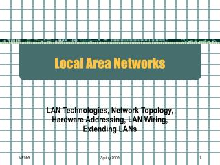
10 Hub Ethernet All nodes share 10 Mbps One device sending at a time Hubs • Ethernet concentrator • “Self-contained” Ethernet LAN in a box • Passive • Works at physical layer 1
Hubs (more explanation) • The purpose of a hub is to regenerate and retime network signals. • Similar characteristics to those of the repeater. • The difference between a repeater and a hub is the number of cables that connect to the device. Whereas a repeater typically has only 2 ports, a hub generally has from 4 to 20 or more ports. • Whereas a repeater receives on one port and repeats on the other, a hub receives on one port and transmits on all other ports. • The following are the most important properties of hubs: • Hubs amplify and propagate signals through the network. • Hubs do not require filtering, or path determination or switching. • Hubs are used as network concentration points. • Hubs are used most commonly in Ethernet 10BASE-T or 100BASE-T networks. • Hubs are used to create a central connection point for the wiring media and to increase the reliability of the network. Allowing any single cable to fail without disrupting the entire network increases the reliability of the network. This feature differs from the bus topology where having one cable fail disrupts the entire network. (Network topology is discussed later in this module.) Hubs are considered Layer 1 devices because they only regenerate the signal and repeat it out all of their ports (network connections).
Bridge (1) • works at the layer 2 (requires software) • connects two networks of the same type • LAN to LAN (example: WLAN to Fast Ethernet) • forwards data (1 packet @ the time) depending on the destination address in the data packet (not the IP address, but the physical (MAC) address that is unique for every Network Interface Card (NIC)) • all computers are in the same sub-network • packet filtering • separates collision domains – larger network spans • a stand alone device or a PC with the special NIC and the accompanied software
Bridges explained (1) • A bridge is a Layer 2 device designed to create two or more LAN segments, each of which is a separate collision domain. That is, they were designed to create more useable bandwidth. The purpose of a bridge is to filter traffic on a LAN—to keep local traffic local—yet allow connectivity to other parts (segments) of the LAN for traffic that is directed there. You might wonder, then, how the bridge knows which traffic is local and which is not. The answer is the same one the postal service uses when asked how it knows which mail is local. It looks at the local address. Every networking device has a unique MAC address on the NIC. The bridge keeps track of which MAC addresses are on each side of the bridge and makes its decisions based on this MAC address list. • Bridges filter network traffic by looking only at the MAC address. Therefore, they can rapidly forward traffic representing any network layer protocol. Because bridges look only at MAC addresses, they are not concerned with network layer protocols. Consequently, bridges are concerned only with passing or not passing frames, based on their destination MAC addresses. • The following are the important properties of bridges: • Bridges are more intelligent than hubs—that is, they can analyze incoming frames and forward (or drop) them based on addressing information. Bridges collect and pass packets between two or more LAN segments. • Bridges create more collision domains, allowing more than one device to transmit simultaneously without causing a collision. • Bridges maintain address tables.
Bridges explained (2) • What really defines a bridge is its Layer 2 filtering of frames and how this is actually accomplished. Just as was the case of the repeater/hub combination, another device, called a switch (which you learn about next in this section), is used for multiple bridge connections. • In order to filter or selectively deliver network traffic, bridges build tables of all MAC addresses located on a network and other networks and map them. • If data comes along the network media, a bridge compares the destination MAC address carried by the data to MAC addresses contained in its tables. • If the bridge determines that the destination MAC address of the data is from the same network segment as the source, it does not forward the data to other segments of the network. • If the bridge determines that the destination MAC address of the data is not from the same network segment as the source, it forwards the data to the appropriate segment. • By performing this process, bridges can significantly reduce the amount of traffic between network segments by eliminating unnecessary traffic.
Switch (1) • basically a multi-port bridge • provides a better network performance • forwards more than a single packet at a time • separates collision domains – larger total network span • bandwidth not shared
Switches explained • Switches, also referred to as LAN switches often replace shared hubs and work with existing cable infrastructures to ensure that they are installed with minimal disruption of existing networks. • Like bridges, switches connect LAN segments, use a table of MAC addresses to determine the segment on which a datagram needs to be transmitted, and reduce traffic. Switches operate at much higher speeds than bridges, and can support new functionality, such as virtual LANs. • Switches are data link layer devices that, like bridges, enable multiple physical LAN segments to be interconnected into single larger network. Similar to bridges, switches forward and flood traffic based on MAC addresses. Because switching is performed in hardware instead of in software, it is significantly faster. You can think of each switch port as a microbridge; this process is called microsegmentation. • Thus each switch port acts as a separate bridge and gives the full bandwidth of the medium to each host.
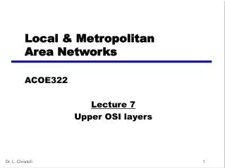
Switched Ethernet Ethernet Switch 10 Backbone Each Node has 10 Mbps Multiple devices sending at the same time Switches—Layer 2
10 Switched Ethernet 10 Switches versus Hubs Hub Ethernet One device sending at a time All nodes share 10 Mbps Ethernet Switch Backbone Multiple devices sending at the same time Each node has 10 Mbps
Router • connects different sub-networks • Layer 3 (Network layer) device • forwarding of packets (routing) is based on IP addresses not on MAC addresses • more expensive than a switch (requires CPU) • Layer 3 switches (only work with IP packets)
Gateway • A gateway is a network point that acts as an entrance to another network. On the internet, in terms of routing, the network consists of gateway nodes and host nodes. • Host nodes are computer of network users and the computers that serve contents (such as Web pages). • Gateway nodes are computers that control traffic within your company’s network or at your local internet service provider (ISP)
What is the difference between? • Bridge: device to interconnect two LANs that use the SAME Logical Link Control protocol but may use different medium access control protocols. • Router: device to interconnect SIMILAR networks, e.g. similar protocols and workstations and servers • Gateway: device to interconnect DISSIMILAR protocols and servers, and Macintosh and IBM LANs and equipment
Internetworking example (1) a simple internet
2. Wide Area Networks 2.1 ISDN and Broadband ISDN 2.2 X.25 2.3 Frame Relay 2.4 ATM
Integration of Voice, Video & Data • Also called “Convergence” • Networks that were previously transmitted using separate networks will merge into a single, high speed, multimedia network in the near future • First step (already underway) • Integration of voice and data • Next Step • Video merging with voice and data • Will take longer partly due to the high data rates required for video
2.1 Integrated Services Digital Network (ISDN) • Was develop by ITU-T in 1976 • Combines digital telephony and data transport services • Aim is to digitise the telephone network so that it allows the integration and transmission of voice, data and video over existing telephone lines • The goal of ISDN is to form a wide area network that provides universal end-to-end connectivity over digital media
ISDN Services • Bearer services: • Provide the means to transfer information (voice, data and video) between without changing the content of the information • Teleservices: • The network may changed or process the contents of the data • Rely on the facilities of the bearer services • Supplementary services: • Provide additional functionality to the bearer services and the teleservices
History (1) • Voice communication over analog networks • Telecommunications networks were entirely analog • Voice and data communications over analog networks • Modems will developed to allow digital exchanges over existing analog lines • Analog and digital services to subscribers • Add digital technologies while continuing analog services
History (2) • Integrated digital network (IDN) • A combination of networks available for different purposes • Allows a variety of networks – packet switched, circuit switched • Digital pipes – using time-multiplexed channels sharing very-high-speed paths • Integrated services digital network (ISDN) • All the services are in digital • Voice are digitised • Allow all communication connections to occur via a single interface
Channels • ISDN standard defines three channels with different transmission rate: • Channel B (Bearer): 64kbps • Channel D (Data): 16kbps, 64 kbps • Channel H (Hybrid): 384 (H0), 1536 (H11), 1920 (H12) kbps
Interface types • Two types of digital subscriber loops: • Basic rate interface (BRI): • consisting of two B channels and one 16 kbps D channel (2B+D) • Used in residential and small office • User-to-user communication • Primary rate interface (PRI): consisting 30 B channels and one 64 kbps D channel (30B+D) • User-to-network communication • LAN connect to other LANs
Broadband ISDN • The original ISDN is known as narrowband ISDN (N-ISDN) • As technology advances, N-ISDN is not enough to cope with the requirement. • Broadband ISDN (B-ISDN) is developed to provide for the needs for the next generation, with data rates in the range of 600 Mbps (400 times faster than the PRI) • B-ISDN is based on the change from metal cable to fiber-optic cable.
B-ISDN: Types of Services • Interactive: • Those that require two-way exchanges between either two subscribers or between a subscriber and a service provider • There are three types: • Conversational: phone calls or real time services (video telephony, video conferencing) • Messaging: store and forward exchanges (voice mail, data mail, video mail) • Retrieval: retrieve information from information centre (videotex: allows subscribers to select video data from an on-line library)
B-ISDN: Types of Services • Distributive: • Unidirectional sent from provider to subscribers • Without user control: broadcast to user without user’s having requested them or having control over either broadcast times or content (commercial TV) • With user control: broadcast to user in a round-robin fashion (educational broadcasting, pay TV – a program is made available in a limited number of time slots, a user need to activate the television to receive it)
2.2 X.25 • It is a packet switching wide area network • Introduced in 1976 • Interface between host and packet switched network • Almost universal on packet switched networks and packet switching in ISDN • Defines three layers • Physical • Link • Packet
X.25 Layers • Physical • Interface between attached station and link to node • Data terminal equipment DTE (user equipment) • Data circuit terminating equipment DCE (node) • Uses physical layer specification X.21 • Reliable transfer across physical link • Sequence of frames • Link • Link Access Protocol Balanced (LAPB) • Subset of HDLC • Packet • External virtual circuits • Logical connections (virtual circuits) between subscribers
Virtual Circuit Service • Virtual Call • Dynamically established • Permanent Virtual Circuit (PVC) • Fixed network assigned virtual circuit • Multiplexing • DTE can establish 4095 simultaneous virtual circuits with other DTEs over a single DTC-DCE link • Packets contain 12 bit virtual circuit number
2.3 Frame Relay • Designed to be more efficient than X.25 • Developed before ATM • Larger installed base than ATM • ATM now of more interest on high speed networks
Frame Relay - Differences • Call control carried in separate logical connection • Multiplexing and switching at layer 2 • Eliminates one layer of processing • No hop-by-hop error or flow control • End to end flow and error control (if used) are done by higher layer • Single user data frame sent from source to destination and ACK (from higher layer) sent back
Comparing Frame Relay • Advantages: • Operates at higher speed • Operates in just the physical and data link layers – can be used easily as a backbone network to provide services to protocols that already have a network layer protocol • Allows bursty data – do not have fixed data rate, user can send 6Mbps for 2 sec, 3.44Mbps for 1 sec and nothing for 7sec • Allows a frame size of 9000 bytes which is enough for all LAN frames • Less expensive than other traditional WANs
Comparing Frame Relay • Disadvantages: • Although can operate at 44.376 Mbps but is still not high enough for protocols with higher data rates (B-ISDN) • As it allows variable length frames – may create varying delays for different users • Because of varying delay, it is not suitable to send sensitive data like real time voice or video
Control Plane • Between subscriber and network • Separate logical channel used • Similar to common channel signaling for circuit switching services • Data link layer • LAPD (Q.921) • Reliable data link control • Error and flow control • Between user (TE) and network (NT) • Used for exchange of Q.933 control signal messages
User Plane • End to end functionality • Transfer of info between ends • LAPF (Link Access Procedure for Frame Mode Bearer Services) Q.922 • Frame delimiting, alignment and transparency • Frame mux and demux using addressing field • Ensure frame is integral number of octets (zero bit insertion/extraction) • Ensure frame is neither too long nor short • Detection of transmission errors • Congestion control functions
Frame Relay Virtual Circuits • Frame relay is a virtual circuit that does not use physical addresses to define the DTEs connected to the network • In frame relay, the virtual circuit network sits in data link layer and not in network layer like in X.25 • It is identified by a number called data link connection identifier (DLCI) • When a network established a virtual circuit, a DTE is given a DLCI number and the local DTE uses this DLCI to send frame to the remote DTE • There are two types of VC: • Permanent VC • Switched VC
Factors of Frame Relay Traffic • Committed Information Rate (CIR) • defines an average rate in bits per second • Excess burst size • defines the maximum number of bits in excess of committed burst size that a user can send during a predefined period of time.
2.4 Asynchronous Transfer Mode (ATM) • ATM can transmit voice, video and data across LANs, MANs, and WANs. • ATM is an international standard that implements a high-speed, connection-oriented, cell-switching, and multiplexing technology that is designed to provide users with virtually unlimited bandwidth. • ATM is the cell relay protocol • The combination of ATM and B-ISDN will allow high speed interconnection of all of the world’s network