Download
1 / 27
270 likes | 388 Views
Design of 200MeV KEK-ERL Test facility by using SAD. Miho SHIMADA, Accelerator Laboratory, KEK (Present affiliation , UVSOR, IMS). Energy Recovery Linac (ERL). Beam energy were recovered and putted into the following bunch High coherency, low emittance and short bunch beam. Injector.

E N D
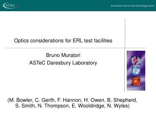
Design of 200MeV KEK-ERL Test facility by using SAD Miho SHIMADA, Accelerator Laboratory, KEK (Present affiliation , UVSOR, IMS)
Energy Recovery Linac (ERL) • Beam energy were recovered and putted into the following bunch • High coherency, low emittance and short bunch beam Injector Damping Accelerate or deaccelerate 5GeV ERL planned by KEK
Plan of 200MeV KEK-ERL Test Facility (~2005 year) 40m Injection Damp
Merging optics • The merging optics comprise • 4 quadrupolesfor matching the injector lattice functions into the linac • 4 dipoleschicane for merging the injector to main linac. Merger RF section TBA Merger
Optics up to the insertion devices Matching point 1 Initial condition Matching point 2 Matching point 3 • Initial condition • bx=58m, by =51m, • ax=ay=0, hx=hy=h’x=h’y=0 • Matching point 1, 3 • ax=ay=0, hx=hy=h’x=h’y=0 • Matching point 2 • ax=ay=0, hx=hy=h’x=h’y=0 Undulator Merger RF section TBA Merger
Parameters of ERL Test Facility • Max. beam energy : 205 MeV • Max. average beam current : 100 mA • Max. bunch charge : 77 pC • Operating frequency : 1.3 GHz • Normalized transverse emittance (x/y) : 100nm rad • Rms bunch length : 1 ps → 0.1ps • Rms energy spread : 5×10⁻⁵ • RF cavity gradient : 20 MV /m • Injection beam energy : 5 MeV • R56 in one TBA : -0.7 ~ 0.0
Required beam quality • Small normalized emittanceepnx <100nm rad • Short bunch sz~ 0.1 psec • High current ~ 100mA • High efficiency energy recovery etc • Simulation • Emittance growth due to Coherent Synchrotron Radiation (CSR) at the chicane with low energy(Kim et al) • Emittance growth due to HOMs in multi-bunch(Kim et al) • Emittance growth in the arc section for bunh compression • Efficiency of beam energy recover after bunch compression
Emittance growth due to CSR wake • Emittance growth caused by the aberration from the nominal orbit by the energy change due to coherent synchrotron radiation (CSR). r : bending radius sz : rms bunch length q : charge per bunch
Bending angle in merging dipoles should be as small as possible to minimize the influence of CSR on the beam emittance. 1. Optimization of the optics of the merger (Kim et al) Minimization of Emittance growth
Optimization of the merger section for minimization of the emittance growth due to CSR • Optimization of the length of the drifts and bx, by at the injection • q=37pC, sz=1 psec, enx =100nm・rad 207 nm・rad 150 nm・rad No Optimized Optimized
2. Emittance growth due to HOM in Multi-bunch (Kim et al) A resonator wake by RF HOM • R/Q = 23.8 x10⁴ [Ohm/m2] : Tesla type
Emittance by continuous 1000 bunches passage (Offset in x and y directions = 10 micron)
HOM CSR Multi-bunch instability due to RF HOMs and CSR effect 320 bunches, q=37pC, sz=1 psec, e nx = 100mm・mrad • R/Q= 23.8D4, fh=2.5752D9, Q=5D4 • R/Q=8.69D4, fh=1.8722D9, Q=7D4 • R/Q=6.54D4, fh=1.8642D9, Q=5D4 If sz = 1 psec, the emittance growth is caused by HOM rather than CSR.
Bunch compression and emittance growth due to CSR • Bunch compression is performed at the arc section
Bunch compression at the arc How to optimize the bunch compression? • R56 of ARC section was varied from 0 to -0.7 m. • RF phase shift, fRF, was controlled. • Broaden the energy spread, sE.
Additional two quadrupole magnets • Controllable range in R56 is widen from -0.3~0 to -0.7~0 two quadrupole were added
Matching qCSR and qPhase at the end of the fourth bending magnet When the direction of the transverse phase space, qPhase, is parallel to the direction of the CSR kick, qCSR, the emittance growth can be minimized. Emittance growth is large Minimized emittance growth a, b, g : Twiss parameter f, r : Bending angle and radius
qPhasewas controlled by changing twiss parameter a at the end of the fourth bending magnet Controllable range inqPhaseis depend on R56 According to the left graph, qCSRagree well with qPhaseat R56 = -0.5 m. Theemittance growth can be minimized around it. qPhase vs. R56 qCSR qPhase qCSR and qPhase at a=-3
Longitudinal Phase space Sharp peak → Large CSR Smooth shape → Small CSR
Transverse Phase Space Large CSR Mismatch qPhase and qCSR BEST OPTICS
4.Energy recovery after bunching • The optics of ARC 1 and ARC 2 are not symmetry because the longitudianal phase space is not accurately upright at the insertion device. • R56 of ARC 2 was controlled under the condition that R56 of ARC 1 is -0.4, q is 19.4 C, in which ex~200nm・rad at the insertion devices. ARC 1 ARC 2
Relationship sz beginning of the cavity for energy recovery andR56 of ARC 2 • In no CSR case, the optimum optics to recover the bunch length, 1 psec, is R56 = -0.5 m. • In CSR case, small R56 is enough to recover the bunch length, which is extended by CSR. Large Rotation Small Rotation
The figure shows the change in the energy before and after the cavity for energy recovery. Efficiency of energy recovery is high for a short bunch. Residual energy after the energy recovery and R56 of ARC section for return Short bunch at the deaccelerate cavity Long bunch at the deaccelerate cavity
Energy distribution after the cavity for energy recovery (energy recovery+energy loss due to CSR) R56 = -0.2 m R56 = -0.3 m R56 = -0.44 m • Short bunch • High efficiency • Inhomogeneous • Long bunch • Low efficiency • Homogeneous
Summary • In the case of 1 psec electron bunch, HOM is more critical issue for the emittance growth than CSR. • By optimization of arc section, 30mA is achieved with keeping the condition that epnx>200nm rad and sz< 0.1psec (30mm) at the insertion device. • For high efficiency energy recovery, the bunch length should not be recovered but remain to be short. • In some simulation, we employed ERL Track developed by K. Yokoya, which is similar to SAD and work on Windows platform.