Download
1 / 59
650 likes | 1.34k Views
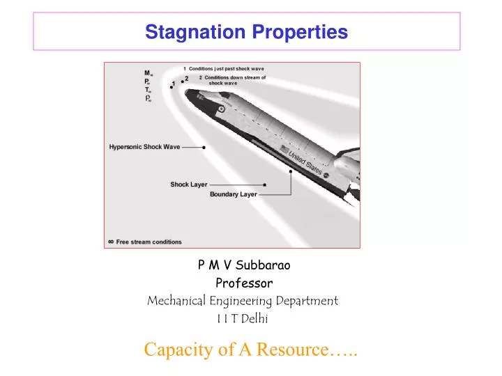
Stagnation Properties . P M V Subbarao Professor Mechanical Engineering Department I I T Delhi. Capacity of A Resource…. 1. Stagnation Properties of Isentropic Flow. What was Stagnation Temperature At Columbia Breakup. Loss Of Signal at: 61.2 km altitude ~18.0 Mach Number.

E N D
Stagnation Properties P M V Subbarao Professor Mechanical Engineering Department I I T Delhi Capacity of A Resource…..
1 Stagnation Properties of Isentropic Flow
What was Stagnation Temperature At Columbia Breakup Loss Of Signal at: 61.2 km altitude ~18.0 Mach Number T∞ ~ 243 K
Ideal & Calorically perfect Gas Ideal Gas with Variable Properties Real Gas with Variable Properties
Capacity of A Cross Section Mass flow rate through any cross section of area A Maximum Capacity is obtained when sonic velocity occurs at throat !
Specific Mass flow Rate Mass flow rate per unit area of cross section:
Design of Supersonic Intake / Nozzle P M V Subbarao Associate Professor Mechanical Engineering Department I I T Delhi From the Beginning to the Peak or Vice Versa….
Distinction Between True 1-D Flow and Quasi 1-D Flow • In “true” 1-D flow Cross sectional area is strictly constant • In quasi-1-D flow, cross section varies as a Function of the longitudinal coordinate, x • Flow Properties are assumed constant across any cross-section • Analytical simplification very useful for evaluating Flow properties in Nozzles, tubes, ducts, and diffusers. Where the cross sectional area is large when compared to length
Specific Mass flow Rate Mass flow rate per unit area of cross section:
Maximum Capacity of An Intake/Nozzle • Consider a discontinuity at throat “choked-flow” Nozzle … (I.e. M=1 at Throat) • Then comparing the massflow /unit area at throat to some other station.
Design Analysis For a known value of Mach number, it is easy to calculate area ratio. Throat area sizing is the first step in the design. If we know the details of the resource/requirements, we can calculate the size of throat.
Cryogenic Rocket Engines A ratio of LO2:LH2 =6:1 T0 = 3300K. P0 = 20.4 Mpa
Specifications of A Rocket Engine • Specific Impulse is a commonly used measure of performance For Rocket Engines,and for steady state-engine operation is defined As: • At 100% Throttle a RE has the Following performance characteristics Fvacuum = 2298 kNt Ispvacuum = 450 sec. Fsea level = 1600 kNt
Design Procedure Select a technology : Isp & Fthrust
SEA Level Performance One needs to know the Mach number distribution for a given geometric design! Find the roots of the non-linear equation.
Numerical Solution for Mach Number Caluculation • Use “Newton’s Method” to extract numerical solution • Define: • At correct Mach number (for given A/A*) … • Expand F(M) is Taylor’s series about some arbitrary Mach number M(j)
• From Earlier Definition , thus Still exact expression • if M(j) is chosen to be “close” to M And we can truncate after the first order terms with “little” Loss of accuracy
• First Order approximation of solution for M “Hat” indicates that solution is no longer exact • However; one would anticipate that “estimate is closer than original guess”
• If we substitute back into the approximate expression • And we would anticipate that “refined estimate” …. Iteration 1
• Abstracting to a “jth” iteration Iterate until convergence j={0,1,….} • Drop from loop when
• Temperature T0 = 3300K Tthroat = 2933.3 K
• Pressure P0 = 20.4Mpa Pthroat = 11.32 MPa
Operating Characteristics of Nozzles P M V Subbarao Professor Mechanical Engineering Department I I T Delhi Realizing New Events of Physics…….
Converging Nozzle pb = Back Pressure Design Variables: Outlet Condition: p0 pb
Designed Exit Conditions Under design conditions the pressure at the exit plane of the nozzle is applied back pressure.
Profile of the Nozzle At design Conditions:
Remarks on Isentropic Nozzle Design • Length of the nozzle is immaterial for an isentropic nozzle. • Strength requirements of nozzle material may decide the nozzle length. • Either Mach number variation or Area variation or Pressure variation is specified as a function or arbitrary length unit. • Nozzle design attains maximum capacity when the exit Mach number is unity.
Converging Nozzle p0 Pb,critical
Operational Characteristics of Nozzles • A variable area passage designed to accelerate the a gas flow is considered for study. • The concern here is with the effect of changes in the upstream and downstream pressures • on the nature of the inside flow and • on the mass flow rate through a nozzle. • Four different cases considered for analysis are: • Converging nozzle with constant upstream conditions. • Converging-diverging nozzle with constant upstream conditions. • Converging nozzle with constant downstream conditions. • Converging-diverging nozzle with constant downstream conditions.
pb,critical<pb2<p0 pb,critical<pb3<p0 Pressure Distribution in Under Expanded Nozzle pb=p0 p0 pb,critical<pb1<p0 Pb,critical At all the above conditions, the pressure at the exit plane of nozzle, pexit = pb.
Convergent-Divergent Nozzle with High Back Pressure p*< pb1<p0 pthroat> p*