Download
1 / 42
420 likes | 539 Views
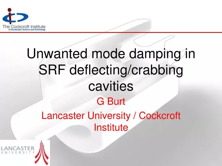
Unwanted mode damping in SRF deflecting/crabbing cavities. G Burt Lancaster University / Cockcroft Institute. Acknowledgements. Lower and Higher Order Modes. TM 010 accelerating mode. Higher order modes. TM 110v (SOM). Need to extract the fundamental mode. TM 011 (HOM).

E N D
Unwanted mode damping in SRF deflecting/crabbing cavities G Burt Lancaster University / Cockcroft Institute
Lower and Higher Order Modes TM010 accelerating mode Higher order modes TM110v (SOM) Need to extract the fundamental mode TM011 (HOM) As we are not using the fundamental accelerating mode, this mode becomes a source of instability. As its frequency is lower than the dipole modes we call it the lower order mode (LOM). frequency Beam-pipe cut-off TE111 (HOM) TM110h crabbing mode
Monopole mode The crabbing mode is not the lowest frequency mode in the cavity, there is usually a lower order monopole mode (LOM) In all cavities the fundamental dipole penetrates further into the beampipe than the fundamental monopole mode. In order to damp the monopole we must either, • Penetrate the coupler further into the beampipe • or • Couple directly into the cavity, on-cell damping
LOM Dampers There are several ways to achieve this, we will review three concepts here (you could also just put the coupler very close to the cavity) On-cell waveguide Coaxial beampipes L-shaped probes
Crabbing mode rejection • Filters are not required as the dipole mode has many field nulls and asymmetries we can take advantage of. Esurf • For a coaxial beampipe the asymmetry of the dipole mode means it will not couple to the TEM mode of the coax. • For beampipe or on-cell couplers we can place the coupler in the vertical plane where the fields are zero. Hsurf B-field
KEK KEK Coaxial Damper • KEK installed the first crab cavity, and their design was based on a coaxial beampipe. • The beampipe TEM mode coupled to the LOM but not the dipole mode. • There were issues with alignment and cooling A filter is added to reject crabbing mode when misaligned
FPC HOM SLAC Coaxial beampipe • Another novel scheme uses a hollow coaxial beam-pipe like the original KEKB cavity. • However this design has the coax e-beam welded to the beam-pipe and a 2nd coax to remove the LOM and SOM to achieve Q’s of around 250. • This is easier to align but difficult to manufacture. • Multipactor may also be an issue SRF 2009 Berlin
Lancaster, FNAL and SLAC L-shaped Probe For the ILC a more standard HOM coupler was proposed. However the tip was bent into an L-shape to provide penetration further towards the cavity.
Jlab and ANL On-Cell damping • It is also possible to couple to the cavity equator rather than the beampipe. • A prototype of cavity utilising this scheme has been developed at TJNAF, using the SPXcrab cavity design. • The first SPXon-cell damper structure was made directly by machining the equators’ slot to match a “saddle” adapter in a 3-D contour.
Jlab and ANL Argonne/Jlab SPX cavity Baseline (Mark-I) Input Coupler • It is not the baseline design (which is a standard waveguide coupler) due to the novel and untested nature of this scheme. • The baseline just uses waveguides very close to the cavity. • The on-cell damping waveguide is suitable for crab cavities as the fields of the crabbing mode are very small in this region compared to the peak fields in the iris (but still creates a hot spot). HOM Dampers LOM Damper Alternate (Mark-II)
Jlab and ANL Recent Cold Test Result for CC-A2 Cavity
Lancaster and Jlab On-Cell Damping LHC A 2-cell on-cell damped cavity was proposed for the LHC global scheme. Each cell as an on-cell waveguide which damps the SOM and the LOM to Q’s below 100. SOM and LOM Coupler Input Coupler HOM Damper SRF 2009 Berlin
KEK Super KEK-B KEK have proposed a coaxial on-cell LOM damper for SuperKEKB and also for the LHC. The inner conductor of the coax stretches across the cavity for maximum LOM damping. This design also has on-cell waveguide damping for the SOM and HOMs. E-Peak B-Peak B-field E-field SRF 2009 Berlin
Mode Polarisation • Dipole modes have a distinct polarisation ie the field points in a given direction and the kick is in one plane. • In a cylindrically symmetric cavity this polarisation could take any angle. • In order to set the polarisation we make the cavity slightly asymmetric. • This will set up two dipole modes in the cavity each at 90 degrees to each other. One mode will be the operating mode, the other is refered to as the same order mode (SOM) and is unwanted.
Polarisation split • It is often necessary to shift the frequency of the SOM to move it away from the crabbing mode. • This is done by squashing the cavity Vertical polarisation Operating mode in horizontal plane
Beam Delivery System optics The crab cavity has to be close to the IP for phase synchronisation issues and needs a large beat function to maximise the kick. The positioning of the crab cavity at a region with a large beta function means that wakefield kicks are not focussed effectively.
Lancaster and FNAL Modal Calculations in MAFIA Operating and Same Order modes at 3.9 GHz High impedance monopole modes are not a problem Lower Order Modes, 2.8 GHz Narrowband dipole modes seen up to 18 GHz High dipole impedances seen at 10 GHz and 13 GHz Trapped 5th dipole passband at 8 GHz 1st Dipole passband
Sum wake A long range wakefield is a superposition of the fields created by each bunch. It is useful to find the frequency dependence of the sum wake. As we sweep through the frequency errors we see that we see resonances with the bunch. Calculating the damping tolerances using this method is slow. However each resonance is due to a single mode hence a single-mode analysis of the damping requirements is valid. If the bunches all arrive at regular intervals and the same offset then the wakefield will tend to a finite constant value known as the sum wake.
Resonances • As you are summing the contribution to the wake from all previous bunches, resonances can appear. For longitudinal wakes we sum hence resonances appear when • It is more complex for transverse wakes as the sum is • However we can find the resonances from the single-mode wake equation Using The solution of which is
Single-Mode Sum Wake The single mode wakefield is given as 4 5 5 5 5 where 5 5 5 = Tb, d = Tb/Td,
Finite Bunch trains 5 5 5 Depending on the Q factor, the sum wake can be reached very quickly, for the ILC we are likely to reach the sum wake within a few hundred bunches.
Solving for Q We can rearrange the single-mode wakefield equation for the sum wake as a quadratic equation. Where And FImax is the maximum allowable wakefield normalised by R/Q The solution of this equation is Giving a Q requirement of
Damping Requirements Inserting the frequencies of the resonances into the single damping solution already derived gives Beam-pipe cut-off This is the damping required to keep the wakefields below the level FImax, for the worst case wakefields. These specs are not tough but might need checking Trapped modes might need attention Same Order Mode, tough spec, requires active damping
Lancaster, CERN and Manchester PLACET The PLACET results show when the damping tolerances are met with a maximum Q of 1x10⁵ the maximum vertical offset is 1.5 nm. The results give good agreement with the previous analytical results.
SOM Tolerances • It is known that for polarised crab cavities the SOM coupler alignment tolerance is given by • Dq~arcsin(QSOM/Qin)1/2 Dq For the LHC this is a tolerance of 50 mdeg(~0.5 mm at the tip) If the cavity is polarised only by the SOM coupler this tolerance is eased by a factor of (DfSOM/Dfmanufacturing)1/2 This is a factor of ~5 for the current design giving a more manageable tolerance of 2.5 mm
SLAC Crabbing mode rejection • SLAC did a study for the LHC elliptical cavities showing the coupling of the SOM coupler to the crabbing mode with an offset • This is in excellent agreement with the theory
SOM Damping If the cavity isn’t using a coaxial beampipe based coupler then the LOM coupler will also damp the SOM. The SOM propagates far into the beampipe so damping is not difficult.
SLAC Alternative Coax-Coax Design An alternative of this design also from SLAC uses a half wave separation between the cells. This allows the addition of a damper to couple to the pi crabbing mode without coupling to the 0 crabbing mode (operating). SRF 2009 Berlin
Compact Crab Cavities R. Calaga, Chamonix ‘12 ~4yr of design evolution Exciting development of new concepts (BNL, CERN, CI-JLAB, FNAL, KEK, ODU/JLAB, SLAC)
l/4 TEM Cavity – BNL (Ilan Ben-Zvi) • Cavity is very short in the direction of opposing beamline. • Nearest HOM is far away.
l/2 TEM Cavity – ODU and SLAC • Using a ½ wave cavity removes any monopole and quadrupole components. • However it then is only compact in one direction (LHC may need both planes). • Also has another monopole mode nearby.
4R crab cavity – Cockcroft - Jlab • The 4 R cavity is ultra compact as it has its half wavelength in the longitudinal plane. • CEBAF have a normal conducting version as a separator. • Has a lower order mode but less HOM’s.
HOM’s in compact cavities As the cavity is compact the frequencies of TE and TM HOM’s are pushed up minimising the total number of modes to be considered. However we now get TEM HOM’s Monopole 3p/4 resonator Dipole 3p/4 resonator
Lancaster, SLAC and ODU HOM damping in compact cavities • The HOMs (and LOM’s) need significant damping due to their location in LHC. • The lowest monopole mode will need a Q ~ 100 and may have up to 6 kW in the HOM/LOM coupler. 4R cavity ¼ wave cavity Each cavity has its own set of couplers, although each set probably works for all cavities. Double ridged cavity
Crab Cavity and Couplers • The 4R cavity use’s on-cell damping, with a demountable coupler concept. • This is complicated due to the lack of horizontal space. Broadband Loop HOM Coupler LOM Coupler Input Coupler
LOM Coupler • We use a resonant loop to damp the LOM at 370 & 940 MHz • External-Q’s down to 100 have been achieved • Crabbing mode does not couple due to symmetry Coupler requirements • The accelerating mode couples strongly to the beam and power could be as much as 6 kW. • Beam stability requires an external Q of ~120 to meet impedance specs. • Complex cavity shape will require a demountable coupler to aid cleaning of the rods.
PBG Crab Cavities A PBG dipole cavity would allow the construction of a crab cavity with no trapped higher order modes. However, one must be careful not to trap other modes in the band-gap as well. CI-SAC Nov 2009
Lancaster and Huddersfield PBG crab cavities We have experimented with various lattice and defect options but initially had difficulty in engineering the perfect dipole bandgap. The monopole mode and the dipole mode were found to be too close in frequency or the bandgap would be too large.
Lancaster and Huddersfield PBG Crab Cavities A solution was found, where the rods around the defect (two missing rods) where enlarged. This pushes the modal frequencies down allowing the monopole to be pushed out of the bandgap.
Conclusion • The lower frequency monopole mode and the same order dipole mode makes unwanted mode suppression in crab cavities more complex than in accelerating cavities. • However several different methods have been proposed (and in some placed proven) by the community.