Download
1 / 27
270 likes | 273 Views
Commissioning of the ATLAS Semiconductor Tracker with Cosmic Rays. Ewa Stanecka / Institute of Nuclear Physics PAS Krakow On behalf of the ATLAS SCT group. Overview. Description of the SCT and the detector modules Detector integration: Modules Barrels “SCT” SCT + TRT

E N D
Commissioning of the ATLAS Semiconductor Tracker with Cosmic Rays Ewa Stanecka / Institute of Nuclear Physics PAS Krakow On behalf of the ATLAS SCT group
Overview • Description of the SCT and the detector modules • Detector integration: • Modules Barrels “SCT” SCT + TRT • Development of DCS system • Tests with cosmic • Operational experience – power supplies, DCS, readout • Detector performance - noise occupancy & efficiency
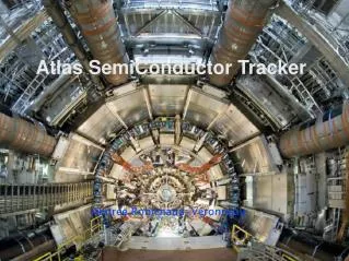
The Inner Detector • Tracking in ATLAS • Silicon Pixel - Silicon Strips - Transition Radiation Tracker
The Barrel module • 4 Sensors • 280 microns thick p-n • (Hamamatsu Photonics) • Strip length 12cm • Pitch 80m • Vmax = 500V 2. 3rd Mounting point 3. Hybrid & Binary Readout chips Flex circuit with 12 x ABCD chips. 7. Overlaps Overlap in r and Z to adjacent modules 4. Be Facing & Central TPG TPG (thermal pyrolythic graphite) plate for sensor cooling 8. Stereo angle Upper or lower detector pairs rotated by 40 mRad 6. Connector Power & Data 5. Module support & Location Holes fix to brackets, one hole & one slot
Structures + Modules + Services Support structures light weight Carbon Fibre barrels • Kapton/Al low mass • tapessupplying LV and HV powerindividually to modules • Optical fibers for data and TTC transmissions and opto-packages CuNi cooling pipes (70μm wall thickness) with integrated module cooling blocks to remove heat through evaporative C3F8 cooling system
Assembled Barrel B6 reception in SR1
Assembly of 4 Barrels • After single barrel test was completed (took 1st half of 2005) started with assembly of 4 barrels together • Barrels are inserted into each other starting with largest to the smallest • Thermal enclosure acts as thermal insulation and electrical shield • Services are folded from each barrel through the thermal enclosure • Frequent checks of cable, fibre, cooling pipe integrity
Final step: SCT and TRT assembled together February 2006 SR1
Tests and development • Modules are tested after • Production (at module assembly sites) • Macro-assembly (at Oxford) • Reception at CERN • Insertion -- only a sector so far (at CERN) • Check that module performance does not change at different stages • Development of “final running” DAQ and DCS software through all these stages • Also used for endcaps • Learnt how to recover errors on modules
DCS Global Control Station Subdetector Control Station Local Control Station PCs PVSS Projects Communication PLC FE System Hardware Common software architecture for all the LHC experiments (PVSS,ELMB)
SCT power supplies • SCT modules are powered by DCisolated, “floating” low voltage (LV)and high voltage (HV) power supplymodules via long, multi-wire lines. INP KRAKOW design • each LV module provides: • “Digital” voltage 4 V 0.5/1.3 A • “Analog” voltage 3.5 V 0.9/1.3 A • Vcsel ctrl. Voltage 1.6 : 6 V 4/6 mA • Photo-diode suppl. 10V 0.6/1 mA • 2 NTC thermistor current sources • RESET/SELECT control levels • each HV module provides: • nominal voltage 0 – 500 V • maximum load 5 mA • voltage ramping rates 50, 20 , 10, 5 V/s • current measurement range 50nA – 5mA • programmable overcurrent protection • overvoltage protection • interlocks
SCT power supplies • The Crate Controller board • - CAN bus communication • custom backplane protocol • SCT specific functions : IV scan, • channel mapping, settings in EEPROM, • safety checks Power supply racks in SR1 building
Cooling, Environmental Monitor & SCT Interlock • ENVIRONMENTAL DCS • Temperature sensors (NTC thermistors) in the outlets of the cooling pipes, the support structure, air temperature inside the detector • Humidity sensors (Xeritron) inside the detector volume • Thermal Enclosure - monitoring of temperature, humidity and pressure • COOLING SYSTEM • Radiation Damage = f(Temperature) -> operational temperature of the detector: -7°C • Initial testing and warm startup at temperatures ~ +15°C • Thermal stability better than 2 °C and tolerance to thermal shocks INTERLOCK SYSTEM
SCT & TRT barrel combined tests • SCT • 486 modules, ¼ SCT barrel 1 top & 1 bottom sector • Keep detector dry using dry air to thermal enclosure • Readout using 12 ROD +1 TIM+1LTP • DCS – final power supply, cooling system, ~200 environmental sensors • 3 scintillators for trigger View from outside towards Side A
Goals of SR1 Commissioning • Detector Operation & Commissioning of System: • Gain experience with detector operation • Test combined detector supply systems • Development of standalone & combined monitoring tools • Commission and test combined readout and trigger • Commission offline SW chain with real data • The detector performance aspects: • TRT performance with SCT inserted and powered • Test 4 SCT barrels together and operation with TRT • Checks of grounding for SCT and TRT • Test synchronous operation and check for X-talk and noise • Collect cosmic for efficiency, alignment & tracking studies
Operational experience • Timing in of SCT modules for the first time and used final ATLAS Local Trigger Processor • Timing across subsystems: (cosmic) LTP trigger - TRT - SCT sectors • Used cosmic coincidences between module sides combined in ROD DSP code • First exercise of data taking in physics mode + passed SCT & TRT data up the full ATLAS DAQ chain • Incl. Monitoring on event filter level and offline • Incl. final data formats and configuration databases used in offline • DCS • Final SCT power supplies, evaporative cooling system, prototypes of final DCS software, interlocks • Long term test of DCS software and supply systems - Like in previous tests but for longer runs during cosmic data taking (stability!) • Verify safety issues • Verify reliability of data exchange with DAQ • Verify reliability of communication among different systems: • Cooling and Power supplies, environmental have to reliably exchange data • Verify performance of PVSS while controlling the detector and at the same time acquiring DCS data
e.g.SCT power supplies • Setup in SR1 with 12 crates (x 48 modules) to supply SCT with power for combined testing • Performance • Long, stable, data-taking runs attempted for the first time • Features complete manual control or usage of predefined states (off, stb, on) loaded in the crate controller’s EEPROM. • Automation of module set-up and turn-on procedures, safety functions, I-V scan, mapping • Low level safety functions proved successful • Satisfactory software performance, CAN bus occupancy • ~7500 parameters monitored every read 15 sec. • Lesson learnt – study of low level temperatures trip in LV PS and appropriate changes in firmware modification
Switch off cooling Start cooling Power up and readout modules Power down modules Stable run e.g.Cooling operation • Used C3F8 evaporative cooling plant to operate detector • Plant close to final works stably and well -> but learned a lot – filtering needed improvement for final system, one capillary had to be unblocked, improvements installed in the final ATLAS system • E.g. Temperature on a cooling pipe during a “warm run” Blocked cooling pipe
Detector PerformanceTests • Many checks of detector performance were done • Standalone calibration tests on SCT after insertion in TRT • Noise studies on SCT in TRT before installation in the pit • Physics-mode running with common readout and trigger for SCT and TRT • Synchronous readout of 4 SCT barrels and SCT+TRT • Noise on SCT from TRT + Noise on TRT from SCT • Test with heater system • Feedback of readout cycle to FE noise • Offline studies with cosmics ongoing • Track Reconstruction • First look at efficiencies in SCT • Residuals • Detector alignment and test/tuning of different alignment methods In this presentation only the noise occupancy and the efficiency are discussed.
Status check on SCT sectors • This is the first full test after the 4-Barrel Assembly • I.e after all barrel handling - service folding - TE mounting and insertion to TRT • Number of functional channels in SCT Barrel: 99.8% • Change of # of functional channels since single barrel tests: 256 of 1536*468 = 0.03% • ENC input noise very similar to values for modules before mounting (after applying temperature correction) <ENC> ~ 1600 e- • Measure ~ 1600 e- ENC at 30C hybrid temperature • reduces at final operation temperature by ~ 5e-/C * 30C Number of chips
Noise Occupancy at 1fC threshold <NO> = 4.5 x 10⁻⁵ SCT Noise Occupancy Found no evidence of significant change of NO during: • Synchronous operation of 4 Barrels • With different trg rate (5Hz-50kHz) • With TRT on / off • With heaters on - off - switching • With different grounding scheme • SCT FE noise during TRT readout cycle <NO> = 4.56 x 10⁻⁵ Number of chips Module production Final in TRT (NO specs: < 5 x 10⁻⁴)
SCT Noise continued • No evidence so far for common mode noise • No increase in noise occupancy during synchronous runs • No correlation between noise hits from chips within a module • No correlation between noise hits on different module Number of hits per event Number of hits per event
The first cosmics in the SCT Barrel • Next are some results for module efficiency in cosmic data …. • Detector timed in (SCT vs TRT vs LTP cosmic trigger) • Run at nominal thresholds (1fC SCT, 1% occ. TRT) • Collected 0.5M cosmic triggers • ~70% with good tracks TRT SCT
First check shows efficiency >99%, as expected from earlier test beam work Eff. vs module most at ~100% 99 % Specification 99% With alignment With dead channel list B5 Low statistics at sector edge First look at SCT efficiency… Example Run 3100
The barrel is now integrated in ATLAS • Pictures from barrel installation in Aug 06 Tests of all 2112 barrel modules with final grounding and shielding scheme are ongoing in the pit.
Summary • The Integration of the SCT is entering its final phase • The Barrel is finished and installed in the cryostat • SCT Tests during the integration phase have shown • 99.8 % of all channels are fully functional • The noise occupancy is well within specs at ~4 x 10⁻⁵ • No crosstalk between SCT and TRT • First steps were taken towards the commissioning of the full tracker with the Combined Test of SCT and TRT barrel and cosmic data taking in SR1 • Tracked cosmics through both barrels and use them for detector checks and to commission the full supply and readout chain • First efficiency and noise-hit studies confirm expected detector performance
Looking forward to see such pictures… …not only in simulation.