Download
1 / 16
160 likes | 288 Views
MICE beam diffuser. M. Apollonio ,P. Lau, W. Lau, J. Tacon, S. Yang – Univ. Oxford. 0. Z=-6010 mm for the upstream face of the diffuser. This is a figure established long time ago (CR, CM14 Osaka - 2006) 1. radial size R as big as possible 2. thickness

E N D
MICE beam diffuser M. Apollonio ,P. Lau, W. Lau, J. Tacon, S. Yang – Univ. Oxford MICE UK- RAL- 2/5/2007
0. Z=-6010 mm for the upstream face of the diffuser. This is a figure established long time ago (CR, CM14 Osaka - 2006) 1. radial size R as big as possible 2. thickness limited number of discs to fulfil MICE configurations 3. mechanics & control design still evolving a) new carousel wheel (to cope with high moment of Inertia) b) motors c) ideas for control (logic) MICE UK- RAL- 2/5/2007
LEADING IDEA trying to exploit all the radial space (15 cm) within the tin can envelope being compatible with mechanical contraints MICE UK- RAL- 2/5/2007
Muons selected on the overall channel ideal disc 7mm 15.5cm 7mm Emi inflation in single layer lead diffuser: 2.8 6.1 mm rad emi(after diff)=6 mm rad MICE UK- RAL- 2/5/2007
7mm 7mm 5cm 15.5cm 7mm Emi inflation with a single layer of lead (small radius): 2.8 5.3 mm rad MICE UK- RAL- 2/5/2007
a more realistic diffuser 7mm 7mm 5cm 15.5cm 7mm 7mm Emi inflation in a staggered lead diffuser: 2.8 6.1 mm rad fixed annulus movable disc + support MICE UK- RAL- 2/5/2007
emi(R)/emi(R=30 cm) single disc staggered discs Pz=148 MeV/c, emi=10mm rad, B=2.9 T Pz=209 MeV/c, emi=10mm rad, B=4 T Pz=267 MeV/c, emi=10mm rad, B=4 T Emittance bias as a function of R_diff (partial inflation) R_diff MICE UK- RAL- 2/5/2007
Proposal to accommodate many configurations STAGGERED/TAPERED with a fixed external annulus …just a sketch (see Peter/Joseph drawings) diffuser tracker envelope 1.5 to 15.5mm 30 cm 24 to 27 cm Supports (outer can/disc support): Al Pb diffuser disc and outer annulus 10 mm MICE UK- RAL- 2/5/2007
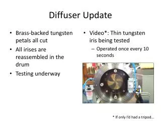
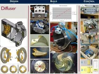
… the real thing J. Tacon MICE UK- RAL- 2/5/2007
How many configurations we need? want? … = 1.4 mm rad un-normalized MICE UK- RAL- 2/5/2007
… maybe 5 discs are enough (at least to begin with) MICE UK- RAL- 2/5/2007
New design for the main carousel: location of air-motors MICE UK- RAL- 2/5/2007
air-motors in the magnetic field can they work ? B (T) 0.32 T R (m) 0.53 T 0.61 T B>= 4T MICE UK- RAL- 2/5/2007 Z (m)
Command: set disc-f for run mode Diffuser Control Flow Chart:main cycle Start: go to Nf Go to empty station NB: need to know WHICH disc is in ! TH empty (mS off)? Which disc is in? Nd Move C to position Nf Move C to position Nd Insert disc Extract disc Go to empty station Go to empty station STOP MICE UK- RAL- 2/5/2007
SUMMARY • diffuser plates will be staggered/tapered discs • of 12.5 cm diameter + outer annulus • thicknesses nearly finalized • some re-design of the mechanics needed • controls in progress: • optical sensors + mswitch • encoding/markers (for wheel position) • air-motors + gear-boxes: • possible SHOW STOPPERs !!! MICE UK- RAL- 2/5/2007