Download
1 / 66
710 likes | 973 Views
UWB 訓練課程 (channel estimation). Speaker :陳昱帆 (Yu-Fan Chen) 日期: 2005.07.31. Outline. Introduction to DS-UWB Systems System Model Receiver Structure UWB Indoor Channel Model The Application of Channel Estimation Technique on DS-UWB Systems The Expectation-Maximization (EM) Algorithm

E N D
UWB訓練課程(channel estimation) Speaker:陳昱帆 (Yu-Fan Chen) 日期:2005.07.31
Outline • Introduction to DS-UWB Systems • System Model • Receiver Structure • UWB Indoor Channel Model • The Application of Channel Estimation Technique on DS-UWB Systems • The Expectation-Maximization (EM) Algorithm • The Application of EM Algorithm on DS-UWB Systems • The Application of Adaptive Filter on DS-UWB Systems • Conventional LMS Adaptive Filter • Fuzzy Step Size LMS Adaptation • The Application of Adaptive Filter on DS-UWB Systems • Joint EM Algorithm and Adaptive Filter for DS-UWB Systems • Conclusion
Introduction to DS-UWB Systems • System Model The transmitted base band signal xk(t) for user k is obtained by spreading a set of BPSK data bits {dk[i]}, onto a spreading waveform sk(t). That is,
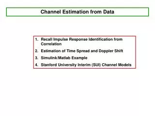
Power time • UWB Indoor Channel Model The UWB indoor channel model is based on the Saleh-Valenzuela (S-V) approach [1] where the impulse response is composed of the exponential decay clusters to model the dense multipath components. The UWB indoor channel model is shown as follows [3]:
The channel impulse response of the IEEE model can be expressed as follows: where X is the shadowing effect, and are the channel amplitude gain, Tl is the delay of the lth cluster, is the delay of the mth ray in cluster l, Lk denotes the total number of propagation paths for user k and is the multipath delay. The channel coefficient can be defined as follows: where and is a log-normal distributed channel coefficient of ray m belonging to cluster l. The term can thus be expressed as follows:
where is assumed to be a Gaussian random variable with mean and standard deviation . Variable , in particular, can be further decomposed as follows: where and are two Gaussian random variable that represent the fluctuations of the channel coefficient on each cluster and on each ray, respectively. Besides, the total energy of the multipath transmission signal must be normalized to unity, that is
The characteristics of UWB channel model. # averaged from 1000 times
Discrete time channel impulse response for UWB channel model 2 – NLOS (0-4m). Discrete time channel impulse response for UWB channel model 1 – LOS (0-4m). Discrete time channel impulse response for UWB channel model 4 – extreme NLOS. Discrete time channel impulse response for UWB channel model 3 – NLOS (4-10m).
Channel Model For the multi-user transmission, the received signal is shown as: where Nu is the number of transmission users, n(t) is the AWGN.
Match Filter • Receiver Structure For user k, the MRC Rake receiver block diagram is shown as follows: The finger of the Rake receiver is regular delayed by Tc to synchronize the multipath signals, and the finger number is properly designed to received the 85% of total transmitted energy.
At the output of the dispreading device, the estimated channel coefficient is multiply at each rake, we assume that the estimated channel coefficient is perfectly estimated and the equation is shown as : Ref.1
Match Filter Synchronization Channel Estimation At the receiver, we use MRC Rake receiver to receiver the multipath signals, for user k, the MRC Rake receiver block diagram is shown as follows:
For Channel Estimation: • The Expectation-Maximization (EM) Algorithm • Fuzzy Step Size LMS adaptive filter
The Application of Channel Estimation Technique on DS-UWB Systems • The Expectation-Maximization (EM) Algorithm [2] Consider a wireless communication in which t transmit antennas send date to r received antennas. The data is unity-energy, BPSK modulated onto a pulse waveform of duration T. Assume that the signal is transmitted through jth transmit antenna and is received by the antenna i. At the output of the Match Filter whose sample rate is 1/T, the received signal is given by
Pilot-Symbol-Assisted Modulation For the multipath fading channel, the author considers that the channel fading is constant during each package, which contains both data and training symbols [2]. The transmitted data matrix for each package can be written as where P denotes the training symbol matrix and is the transmitted data information matrix.At the receiver, we assume that the initial channel coefficient can be estimated by means of the training symbols.
ML Sequence Detector Initial Channel Estimator Channel Estimator • To calculate the original transmitted signal C, it is natural to consider the maximum likelihood detection, i.e. • Therefore, the pdf of H , i.e. p(H|Y,C), need to be derived. • Receiver Structure The EM Algorithm is a general procedure for the iterative computation of maximum likelihood (ML) parameter estimates. The EM-based iterative receiver scheme is shown as follows:
To derive the p(H|Y,C), we need to consider the following pdfs: We employ the Baeys’ rule and combine the above pdfs to obtain: Ref.2
Eventually, the pdf p(H|Y,C) can be shown as follows: Since the p(Y|H,C), p(Y|C), and p(H|C) are Gaussian pdf, the p(H|Y,C) is also a joint Gaussian pdf with mean and row-covariance
With the acquisition of the Q(C|Ci) function, the next step is the maximization step (M-step) that computes the next estimate by now we assume that Given Y and Ci , the step is named as the expectation step (E-step) of the EM algorithm.
We notice that each iteration of the EM algorithm consists of two parts: • channel estimation: • data detection: The initial conditions for the iteration will generally be derived from small number of training symbols. If P denotes the block of training symbols and Yp is the corresponding received sequence, then the initial conditions are
These figures show the (a) BER simulation and (b) channel tracking ability of EM algorithm under Rayleigh fading channel with space-time technique (2Tx., 1Rx.). The package length is 10 bit, and the Rayleigh fading channel is assumed to be constant during each package. (b) (a)
EM Algorithm EM Algorithm Match Filter EM Algorithm ML Sequence Detector Initial Channel Estimator Channel Estimator • The Application of EM Algorithm on DS-UWB Systems • For user k, the combination of MRC Rake receiver and EM algorithm block diagram is shown as follows: • The EM algorithm block diagram is showing as fallow:
Suppose that the channel coefficient in the rth finger is estimated by the EM algorithm, denoted as . We multiple the estimated channel coefficient to the received signal captured by each finger, respectively. Then the summation of each finger is operated and is shown as follows: Then, the received data for user k can be detected by the decision device and denoted as
Performance analysis with UWB indoor channel model The simulation of single user and multi-user transmission for DS-UWB systems that employ EM algorithm is investigated in the following pages. We assume that the package length is 30 bits which contain both 10 bits training symbol and 20 bits data information. Besides, the channel impulse response is fixed during each package.
The simulation of BER for DS-UWB systems that employ EM algorithm with (a) UWB CM1, 6 fingers, (b) UWB CM4, 18 fingers, and single user transmission. (b) (a)
The simulation of BER for DS-UWB systems that employ EM algorithm with (a) UWB CM1, 6 fingers, (b) UWB CM4, 18 fingers, and 5 user transmission. (b) (a)
Summary • Simulation results show that the application of the EM algorithm to the MRC Rake receiver for channel estimation can perform an attractive performance with only a few number of iterations. However, under the multi-user transmission environment, the multi-user interference will severely affect the system performance and eventually cause a poor channel estimation for EM algorithm. • Therefore, in order to reduce the multi-user interference, a novel fuzzy step size LMS adaptive filter is proposed which adopts a variable step size for the interference cancellation. The detailed discussion can be seen in next chapter.
step size Adaptive weight-control mechanism The Application of Adaptive Filter on DS-UWB Systems • Conventional LMS adaptive filter
fast convergence speed a large step size large steady state fluctuation Trade-off slow convergence speed a small step size low steady state fluctuation fast convergence speed variable step size low steady state fluctuation selected by a fuzzy inference system (FIS) • Fuzzy step size LMS adaptation • Introduction For the conventional LMS algorithm: Proposed fuzzy step size LMS algorithm:
Adaptive Filter FIR filter + FLC-LMS/FSPU-LMS ● Defuzzification Interface Fuzzy Rules Based Fuzzification Interface + Delay Inference Engine Fuzzy Inference System (FIS) • Fuzzy Step Size LMS Adaptation The block diagram for the FSSD-LMS and FSPU-LMS algorithm is shown as follows:
For example: • MSE : large (L) , ΔMSE : large (L) • Step size : large (L) • MSE : small (S) , Δ MSE: large (S) • Step size : small (S)
1 0 1 0 1 0 Design Method for FSS-LMS Adaptation In the FIS, the membership functions (MBFs) about inputs and outputs are illustrated in the following figures :
The step size adjustment table for FSSD-LMS algorithm. To derive the variable , the Centroid Calculation of is employed, which returns the center of area under the aggregate MBFs curve, as follows: where q is the output numbers of the Membership Function, is the step size obtained from the Table 4.1 and Table 4.2., is the Membership Function value of x.
1 0 1 0 Design method for FSSD-LMS algorithm • MSE : 0.8M , 0.2S • Δ-MSE : 0.7L , 0.3M
MSE : 0.8M , 0.2S Δ-MSE : 0.7L , 0.3M • MSE : 0.8M , Δ- MSE :0.3M = 0.8 M • MSE : 0.2S , Δ- MSE :0.7L = 0.7 M • MSE : 0.2S , Δ- MSE :0.3M = 0.3 S 3.Design method for FSS_LMS algorithm • MSE : 0.8M , Δ- MSE :0.7L = 0.8 M
Fuzzy Sequential Partial Update LMS Adaptation The tap-weights estimate of the fuzzy sequential partial update LMS (FSPU-LMS) filter at the (i+1)th iteration is written as [5]: Therefore, only coefficients of the vector w(i) are updated at each iteration. The sequential partial update adjustment table for FSSD-LMS algorithm is shown below:
The application of adaptive filter on DS-UWB systems Adaptive Weight Control Matched Filter For user k, the MRC Rake receiver combine with adaptive filter block diagram is shown as follows:
Joint Fuzzy Adaptive Filter for DS-UWB System Adaptive Weight Control Matched Filter Fuzzy Inference System (FIS) Delay For user k, the MRC rake receiver combine with fuzzy step size LMS adaptive filter block diagram is shown as follows:
Performance analysis with UWB indoor channel model Simulation Environment : The simulation of single user and multi-user transmission for DS-UWB systems that adopt the fuzzy step size LMS adaptive filter for the interference cancellation is demonstrated in the following pages. We assume that the package length is 30 bits which contain both 10 bits training symbols and 20 bits data information, the SNR is 20dB, and the channel impulse response is assumed to be fixed during each package.
The simulation of MSE for DS-UWB systems that employ adaptive filter with (a) UWB CM1, 6 fingers, (b) UWB CM4, 18 fingers, and single user transmission. (b) (a)
The simulation of MSE for DS-UWB systems that employ adaptive filter with (a) UWB CM1, 6 fingers, (b) UWB CM4, 18 fingers, and 5 user transmission. (b) (a)
The simulation of Partial Update Parameter (L) for DS-UWB systems that employ fuzzy sequential partial update LMS (FSPU-LMS) adaptive filter with CM1, 6 fingers, and the user number is 1, 5, 10, respectively.
For channel estimation. Interference cancellation. Joint EM Algorithm and Fuzzy Adaptive Filter for DS-UWB Systems • Introduction • The application of EM algorithm on DS-UWB systems: • The application of fuzzy adaptive filter on DS-UWB systems: When under the single user transmission with no MPI and no MUI, the optimum of fuzzy adaptive filter on DS-UWB systems is the same as the channel coefficient in each finger. Therefore, the joint of EM Algorithm and Fuzzy Adaptive Filter for DS-UWB Systems is proposed.
EM Algorithm Adaptive Weight Control EM Algorithm Matched Filter EM Algorithm Fuzzy Inference System (FIS) Delay • The system block of MRC Rake receiver that joint EM algorithm and fuzzy step LMS adaptive filter.
Performance analysis with UWB indoor channel models Simulation Environment : The simulation of single user and multi-user transmission for DS-UWB systems that joint EM and fuzzy adaptive filter is investigated in the following pages. We assume that the package length is 30 bits, the SNR is 20dB, and the channel impulse response is fixed during each package. • The simulation of MSE for DS-UWB systems that joint adaptive filter and EM algorithm with CM1, 6 fingers, and single user transmission.
The simulation of MSE for DS-UWB systems that joint adaptive filter and EM algorithm with CM4, 18 fingers, and single user transmission.
The simulation of MSE for DS-UWB systems that joint adaptive filter and EM algorithm with CM1, 6 fingers, and 5 user transmission.