Download
1 / 37
370 likes | 798 Views
Digital image processing Chapter 11. Image compression. 11. IMAGE COMPRESSION 11.1. Introduction 11.2. Pixel level coding PCM coding Entropic coding RL coding Arithmetic coding 11.3. Predictive coding techniques Principles of the predictive coding Delta modulation 1-D DPCM

E N D
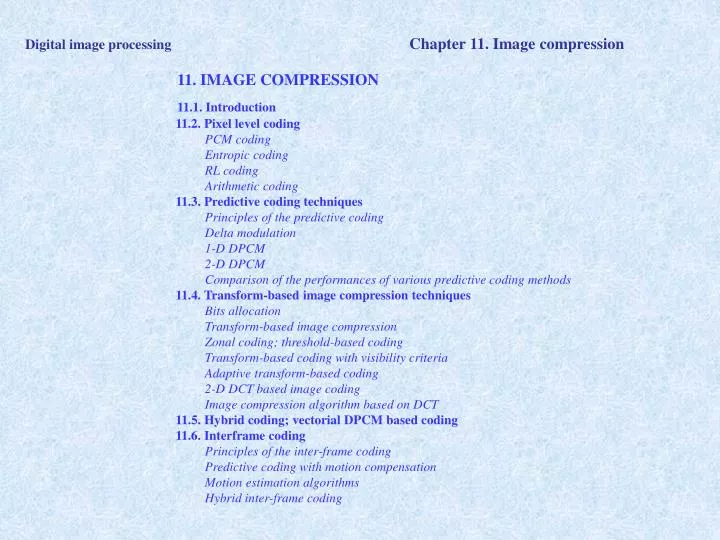
Digital image processingChapter 11. Image compression 11. IMAGE COMPRESSION 11.1. Introduction 11.2. Pixel level coding PCM coding Entropic coding RL coding Arithmetic coding 11.3. Predictive coding techniques Principles of the predictive coding Delta modulation 1-D DPCM 2-D DPCM Comparison of the performances of various predictive coding methods 11.4. Transform-based image compression techniques Bits allocation Transform-based image compression Zonal coding; threshold-based coding Transform-based coding with visibility criteria Adaptive transform-based coding 2-D DCT based image coding Image compression algorithm based on DCT 11.5. Hybrid coding; vectorial DPCM based coding 11.6. Interframe coding Principles of the inter-frame coding Predictive coding with motion compensation Motion estimation algorithms Hybrid inter-frame coding
Digital image processingChapter 11. Image compression • 11. 1. INTRODUCTION • Def.Compression = minimization of the number of bits needed to represent the visual information in the scene, without noticeable loss of information • Applications: • image transmission • image storage in multimedia/image databases
Digital image processingChapter 11. Image compression • The need for image compression: • huge sizes of the data files, in uncompressed form • the storage devices have relatively slow access =>impossible to render/index image info in real time • limited bandwidth of the communication channels=> impossible to do image transmission in real time Memory needed for storage before and after compression • text 2:1, • color images 15:1, • maps 10:1, • stereo sound 6:1, • animation 50:1, • video 50:1.
Digital image processingChapter 11. Image compression • Shannon => the average amount of information per symbol: • L = number of symbols • => It is possible to lossless encode the source having the entropy H by (H+e) bits/symbol, e>0, e->0. • The compression factor (ratio) C: • Maximal (ideal) compression can be achieved by vector quantization (theoretically). Practically – near optimal only:
= average bit rate Digital image processingChapter 11. Image compression • 11. 2. PIXEL LEVEL CODING • 11.2.1. PCM (pulse code modulation) • The minimal number of bits per pixel possible to be achieved by PCM: • 11.2.2. Entropic coding (Huffman) • = coding one block of M pixels,M – small; without compression: B bits/pixel needed => MB bits/block • => the source–has L=2MB symbols => any block can be encoded on less than MB bits, according to: • => entropic coding principle: use a codebook with variable length code words, the length of the code word is different for each block as follows: • - the more frequent blocks (pi large) => have -log2pi smaller => shorter code word • - the less frequent blocks (pi small) => have -log2pi larger => longer code word σ2u= the variance of the signal at the input of the quantizer; σ2q= quantization error
Digital image processingChapter 11. Image compression • Huffman coding algorithm: • Order decreasingly the probabilities pi , i=1,2,…,L, and write them in a list of symbols. • Chose from the list the last 2 elements (with the smallest probabilities, pk , pl) . From the 2 => create a node with the probability pk+pl => and insert it in the ordered list in the right position; erase pk, pl from the list • Asign the codes: 0 to k ; 1 to l • Repeat steps (1)…(3) Symbol pi -log2(pi) Code Subtotal A 15/39 1.38 0 2*15 B 7/39 2.48 111 3*7 C 6/39 2.70 110 3*6 D 6/39 2.70 101 3*6 E 5/39 2.96 100 3*5 Total: 87 bits Binary tree H=87/39=2.23 bits per pixel in average
Digital image processingChapter 11. Image compression • Decoding: Simbol Code A 0 B 111 C 110 D 101 E 100 The received string: 1000100010101010110111 (22 bits) Decode!
Digital image processingChapter 11. Image compression • Versions of the Huffman coding: • * the truncated Huffman code • - first L1 symbols – Huffman encoded; • - the remaining L-L1 are encoded using a prefix code followed by a fixed length code • * the modified Huffman code • - the integer number “i” is represented as i=qL1+j • - encode first L1 symbols with a Huffman code • - if above L1 => encode q by a prefix code + use a terminator code= Huffman code of j • 11.2.3. RLC (run length coding) • => For binary images, 0 – white, 1- black; p(white)>>p(black); encode the length of the white run • => applications: fax; sketches • p(white)=p(0)=p; p(black)=p(1)=q; p→1. • Notations: M = maximum length of a run of zeros; M=2m-1 => m bits to encode the run
Digital image processingChapter 11. Image compression • 11.2.3. RLC - continued • The probability of appearance of a run of l symbols ‘0’, 0 ≤ l ≤ M, followed by a ‘1’: • The average number of symbols/run: • The compression ratio: • The average number of bits per pixel: • The coding efficiency: can be increased by the Huffman coding or by the arithmetic coding of the run lengths (instead of the uniform m bits encoding)
Digital image processingChapter 11. Image compression 11.2.3. The arithmetic coding => A single codeword is used for an entire sequence of symbols => The code = a number in a sub-range of [0;1). => codeword: Any number in [0.0624;0.0688) ex. 0.068 * Decoding: 1) 0.068 [0.0; 0.2) => a1; (0.068-0.0)/(0.2-0.0)=0.34 => 2) 0.34 [0.2; 0.4) => a2; (0.34-0.2)/(0.4-0.2)=0.7
Digital image processingChapter 11. Image compression Arithmetic decoding - continued => 3) 0.7 [0.4; 0.8) => a3; (0.7-0.4)/(0.8-0.4)=0.75 => 4) 0.75 [0.4; 0.8) => a3; (0.75-0.4)/(0.8-0.4)=0.875 => 4) 0.875 [0.8; 1) => a4 => The decoded sequence: a1 a2 a3 a3 a4 * Drawbacks of the arithmetic coding: - limited by the representation precision for long sequences - an end-of-message flag is needed * Alternative solutions: re-normalization and rounding 11.2.4. Bits planes encoding => e.g. 8 planes of 1 bit, independently encoded (MSB …. LSB) => disadvantage: sensitive to errors
Many close to zero data => spatial redundancy, the brightness is almost repeating from a point to the next one! => no need to encode all brightness info, only the new one! Line-by-line difference of the luminance see images: one can “estimate” ( “predict”) the brightness of the subsequent spatial point based on the brightness of the previous (one or more) spatial points = PREDICTIVE CODING Digital image processingChapter 11. Image compression 11. 3. PREDICTIVE CODING 11.3.1. DPCM coding principles = Maximize image compression efficiency by exploiting the spatial redundancy present in an image!
Digital image processingChapter 11. Image compression • 11. 3. PREDICTIVE CODING • 11.3.1. DPCM coding principles – continued – BASIC FORMULATION OF DPCM: • Let {u(m)} – the image pixels, represented on a line by line basis, as a vector. • Consider we already encoded u(0), u(1),…, u(n-1); then at the decoder => only available their decoded versions ( original + coding error), denoted: u•(0), u•(1),…, u•(n-1) • => currently to do: predictive encode u(n), n-current sample: • (1) estimate (predict) the grey level of the nth sample based on the knowledge of the previously encoded neighbor pixels u•(0), u•(1),…, u•(n-1): • (2) compute the prediction error: • (3)quantize the prediction error e(n) and keep the quantized e•(n); encode e•(n) PCM and transmit it. • At the decoder: 1) decode e => gete•(n) + 2) build prediction + 3) construct u•(n): • * The encoding & decoding error:
Basic DPCM codec DPCM codec: (a) with distorsions; (b) without distorsions Digital image processingChapter 11. Image compression 11. 3. PREDICTIVE CODING - continued
Digital image processingChapter 11. Image compression 11.3.2. Delta modulation => the simplest DPCM encoder; prediction from 1 sample, 1 bit quantizer. => alternatively, one can predict the value of the sample as: with: (n)= zero-mean error; - factor which minimizes the mean square error (leak factor); given by the error covariance equation: => SNR can be estimated as:
Delta modulation result for images: q=6,5; =1 Compressed (compression rate 8:1) Original Digital image processingChapter 11. Image compression
Digital image processingChapter 11. Image compression 11.3.2. 1-D DPCM (line-by-line DPCM) => is the usual version of applying DPCM on digital images. The sequence to encode = one image line; consider the sequence {u(n)} stationary => one can use a p order linear predictor: where a(k)are chosen to minimize: **The equations of 1-D DPCM codec: (1) Predictor: (2) Quantizer’s input: (3) Quantizer’s output:e(n) (4) Decoder: => Estimation of the SNR: => Average bit rate reduction vs. PCM:
PCM 8 bits PCM 3 bits The error in 3 DPCM on 3 bits DPCM 3 bits Digital image processingChapter 11. Image compression 11.3.2. 1-D DPCM - Comparison to PCM; the effect of error propagation:
Digital image processingChapter 11. Image compression 11.3.2. 1-D DPCM - Comparison to PCM; the effect of error propagation:
Digital image processingChapter 11. Image compression 11.3.2. 2-D DPCM => prediction as a function of one neighbor on the same line and 3 neighbors on the previous line: with a(k,l)chosen to minimize r(1,0) a1r(0,0) a2r(1,-1) a3r(0,1) a4r(0,1) r(0,1) a1r(1,-1) a2r(0,0) a3r(1,0)a4r(1,-2) r(1,1) a1r(0,1) a2r(1,0) a3r(0,0) a4r(0,2) r(1,-1) a1r(0,1) a2r(1,-2) a3r(0,2) a4r(0,0) 2 E2(m,n) r(0,0) - a1r(1,0) - a2r(0,1) - a3r(1,1) - a4r(1,-1) r(k,l) = covariance of u(m,n). If r(k,l) is separable =>:
Digital image processingChapter 11. Image compression 11.3.2. 2-D DPCM - continued **Equations of 2-D DPCM: (1) Predictor: (2) Quantizer’s input: (3) Quantizer’s output: e(n) (4) Decoder: ** Comparison of the performances of the predictive coding methods:
Digital image processingChapter 11. Image compression • 11.4. TRANSFORM-BASED IMAGE COMPRESSION • ( “block quantization”) • The essence of transform-based image compresssion: • (1) an image block is transformed using a unitary transform, so that a large percent from the energy of the blockis packed in a small number of transform coefficients • (2) the transform coefficients are independently quantized • The optimal transform-based encoder = the encoder which minimizes the mean square error of the decoded data, for a given number of bits the Karhunen-Loeve based encoder. • Transform-based image coding algorithm: • u = a random vector, u[N×1], of zero mean; v=A∙u– a liniar transform of u, so that • v(k) – not correlated => they can be quantized independently => v’(k); u’=B∙v’– inverse transform
Digital image processingChapter 11. Image compression • 11.4.1. Main issues to be solved in transform-based image coding: • Finding the optimal transform matrices: A[N×N], B[N×N], able to minimize the mean square value of the distortion for a given number of bits, D: • Designing the optimal quantizers for v, to minimize D. • Approaches to solve these issues: • For a given quantizer and a forward transform matrix A, the optimal reconstruction matrix B is: • The optimal matrix A from the max. de-correlation p.o.v.= the KLT of u; the lines of A =the eigenvectors of the covariance matrix R of u. Then: B=A-1=A*T. Unfortunately KLT does not have a fast computation algorithm => is typically replaced in compression by: DCT; DST; DFT; Hadamard; Slant good compromise between decorrelation performance & computational speed
Digital image processingChapter 11. Image compression • 11.4.2. Bits allocation: • The variance of v(k) is typically non-uniform => different number of bits needed on each coefficient for the same quantization error; v(k) → nk • The optimal design of the transform-based encoder: how to efficiently allocate the total available number of bits between the transform coefficients, so that D – minimized; for A – some unitary matrix, B=A-1=A*T: • where: σk2 = the variance of v(k); nk = the number of bits allocated for the quantization of v(k); f(nk) = the distortion rate of the quantizer, monotonic, f(0)=1; f(∞)=0. • The transformed-based encoder rate is: ; B= the average number of bits/sample • Bits allocation = finding the optimal nk, nk ≥ 0, which minimizes D for the average number of bits/sample B given.
Digital image processingChapter 11. Image compression • Bits allocation algorithm: (1) Define (2) Find θ = the root of the non-linear equation: (11.30) One encodes only the coefficients having σk2> θ. (3) The number of bits nk is: • (11.31) • => The minimum mean distortion: • (11.32) • If instead of imposing B, one imposes D=d: (1) solve (11.32) => θ; (2) solve (11.31) => nk; (3) estimate B.
Digital image processingChapter 11. Image compression • Practical (simplified) algorithm to allocate the bits for nk - integer: • = iterative algorithm, j – the current iteration: (1) At the beginning of the iterations, set: (2) Compute: (3) If => stop the algorithm. Otherwise repeat (2).
Fig. 11.11Compression rate when using a KLT-based compression scheme Digital image processingChapter 11. Image compression 11.4.3. Transform-based image compression steps: • The image = U[M×N], U={u(m,n)} vector u[MN×1] => A[MN×MN],B[MN×MN], v[MN×1] • In practice: use DCT, DST, DFT, Slant, Hadamard – fast algorithms • Practical implementation of the transform-based image compression: • (1) divide the image in small sized blocks: U[M×N] => I = MN/pq blocks Ui[p×q], i=0,1,…,I-1, • p<<M, q<<N • (2) transform + independently encode the blocks Ui[p×q]. • => Advantages: (a) memory efficient implementation of the transform, MN/pq times • (b) decrease the number of operations for computing the transform on the factor log2MN/log2pq times • Disadvantage: lower compression rate r.
Fig. 11.122-D transform image coding Bit allocation for DCT for 16x16 pixels block Digital image processingChapter 11. Image compression • Practical algorithm for transform-based image compression: • * The steps of the algorithm: • (1) Divide the input image into blocks Ui, transform them 2-D to get Vi, i=0,..., I-1, • (2) Bit allocation:
Digital image processingChapter 11. Image compression • (3) Quantizer design: • (4) Encode the quantizer’s output • (5) Decode & inverse quantization of the coefficients • – at the decoder: • => One can compute: the mean distortion, the mean bit rate:
Digital image processingChapter 11. Image compression • 11.4.4. Zonal coding and threshold-based coding: • Zonal coding:according to the bit allocation matrix => transmit just Nt coeficients = coeficients of the transform with large variances => the zonal mask = mask with values 1 for the sent coefficients, 0 otherwise: • Threshold based coding: transmit only the coefficients having the amplitude above a threshold (regardless their variance); the set of the transmitted coefficients = I’t • = threshold-based mask
Fig.11.16Transform-based codec with visibility criteria (F – the unitary Fourier transform matrix) Digital image processingChapter 11. Image compression 11.4.4. Transformed-based coding with visibility criteria: • 11.4.5. Adaptive transform-based coding: • adapt the transform • adapt the bit allocation • adapt the quantization levels
Fig.11.17The influence of the different DCT coefficients Digital image processingChapter 11. Image compression 11.4.6. 2-D DCT –based coding:
Digital image processingChapter 11. Image compression 11.4.6. 2-D DCT –based coding- continued:
Digital image processingChapter 11. Image compression • DCT-based encoding algorithm:
Digital image processingChapter 11. Image compression • DCT-based encoding algorithm – continued: