Download
1 / 7
70 likes | 180 Views
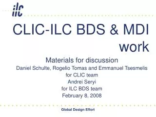
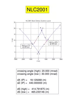
Possible 20 mrad Crossing Angle Geometry for ILC MDI Tom Markiewicz SLAC. TESLA MDI mtg. 26 August 2004. 0.5. 0.4. 113mrad. 0.3. Inst. Mask. W. 0.2. W. 0.1. Pair-LuMon. 46mrad. QD0. 0. LowZ Mask. BeamPipe. Exit radius 2cm @ 3.5m. -0.1. W. W. -0.2. Support Tube. -0.3. ECAL.

E N D
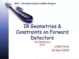
Possible 20 mrad Crossing Angle Geometry for ILC MDITom MarkiewiczSLAC TESLA MDI mtg. 26 August 2004
0.5 0.4 113mrad 0.3 Inst. Mask W 0.2 W 0.1 Pair-LuMon 46mrad QD0 0 LowZ Mask BeamPipe Exit radius 2cm @ 3.5m -0.1 W W -0.2 Support Tube -0.3 ECAL -0.4 HCAL YOKE -0.5 0 0.5 1 1.5 2 2.5 3 3.5 4 SD Forward Masking, Calorimetry & Tracking 2003-06-01
SiD Forward Masking, Calorimetry & Tracking 2004-04-15 SD0 QF1 Q0 LowZ BeamPipe LUMOM QD1 QD2 Support Tube ECAL HCAL EndCap_Muon PacMan
2003-2004 Differences • Switch from W to HCAL as a pairs-shield and the overall shorten in length • This is more aggressive from the point of view of protection from the pair albido/photons.
Changes • The extra-thick W-Si nose-cone 46-113 mrad has been made identical to the ECAL: this is well above the pair deadzone so standard ECAL low-occupancy technology is fine. The junction has changed nominally to 48mrad given the new z position and the size of the pair dead region at that z. • We remove the complicated cylindrical tungsten mask, wedge W mask and Carbon support tube in favor of a clean C-Fiber tube that end-butts onto an HCAL unit. This seems better for the physics and is probably fine for the backgrounds, subject to verification. • The attachment and transfer of weight from the QD0 support (when endcap door is open) to the detector (when door closed and we are in vibration sensitive mode) should be easy. • This is cartooned as the gray wedges joining the support cylinder to the yoke
Changes • While it is not visually evident in the colorized picture, my plan is to have what it appears we are now calling the BeamCal as a device 25mrad in diameter. The z=3.15m radius is then 7.88cm which, at 5 Tesla, is enough to catch all the pairs. Visually it would just cover the face of QD0. • The region not well drawn in the color picture is the 25-48mrad. In the picture it is indistinguishable from BeamCal. It is also in a low occupancy region outside the pair deadcone. I imagine this region covered by a separate ECAL-like disk or by a BeamCal-like disk, but without the fancy timing and with perhaps better resolution readout. Part of my goal in this redesign was to emphasize that the SUSY region that needs aggressive R&D is limited to 25mrad in SiD. One cannot cover this angular region with the "nose-cone" at low z (1.8m) because of the parabola of the pair dead cone, so it is easiest to put it at the back, or, as in the case of the TESLA design, at an intermediate z.
Next Iteration The next version of this picture should explicitly indicate this 25-48mrad (Forward Bhabha monitor?) detector and explicitly call out any spatial pair position detector on the upstream face of BeamCal (if that is the plan).