Download
1 / 14
140 likes | 291 Views
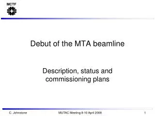
First Beam in the MTA beamline. Description, first beam and further commissioning plans C. Johnstone, F. Garcia, M. Gerardi, B. Higgins, M. Kucera , M. Kufer, D. Newhart – commissioning team. Purpose: MuCool Test Area and Beamline.

E N D
First Beam in the MTA beamline Description, first beam and further commissioning plans C. Johnstone, F. Garcia, M. Gerardi, B. Higgins, M. Kucera , M. Kufer, D. Newhart – commissioning team C. Johnstone All Exp. Meeting 15 Dec 2008 1
Purpose: MuCool Test Area and Beamline • A new experimental area, the Muon Test Area,(2003) has been constructed to develop, test, and verify muon ionization apparatus using the 400-MeV proton beam from the FermilabLinac • Since muon facilities involve the capture, collection and cooling of ~1013muons at a repetition rate of 15 Hz, conclusive tests require ~1013 protons/pulse at 15 Hz (full Linac beam up to safety envelope) • The beamline designed for MTA experiments included specialized insertions for linac beam diagnostics and beam measurements, greatly enhancing the functionality of the beamline. • Installation of the beamline was complete fall, 2008. • As such it represents the only facility in which experiments have direct access to a primary beam C. Johnstone All Exp. Meeting 15 Dec 2008 2
Background/Recent History, MTA Beamline • Original proposal 1995 • Re-proposed for MuCool Test Area • Large-aperture (LANL) magnets • 12” beam-size acceptance for cooling tests • Re-designed for dual purpose • MTA beamline • Re-use existing resources • Modest 2” beam sizes • Linac beam diagnostic line • Transverse emittance measurement • Phase space tomography (w/o dispersion) • Momentum spread measure (high dispersion) C. Johnstone All Exp. Meeting 15 Dec 2008 3
As-built MTA Beamline, Nov., 2007 March, 2007 Beamline installation: F. Garcia Nov, 2007 You are Here To MTA C. Johnstone All Exp. Meeting 15 Dec2008 4
Extraction from Linac • Pulsed C magnet – capable of 15 Hz Linac “pulse” selection • Entire Linac pulse is extracted • – low loss operation C. Johnstone All Exp. Meeting 15 Dec 2008 5
Emittance Measurement section • Takes advantage of shield wall 3 profiles MTA hall 10 m straight between quads 3 MW profile monitors for tomography disp suppressed straight C.Johnstone All Exp. Meeting 15 Dec 2008 6
MTA beam event • Initial startup – • Reuquired dedicated studies (HEP beam) • Booster beam event • Interim configuration - • Parasitic to HEP • Commandeer Linac Study event • Final configuration • Dedicated MTA event TLG • “single-pulse” extraction • Parasitic to HEP C. Johnstone All Exp. Meeting 15 Dec 2008 7
MTA Beam to 1st Beamstop • Initial beam: linac enclosure only • 1st beam stop with present hatch shielding • Beam to Exp Hall • Additional shielding primarily: • Hatch, penetrations, rollup door MTA exp hall 1st beam stop Beampipe exit Beamstop cave C. Johnstone All Exp. Meeting 15 Dec 2008 8
Operational limits, 1st beam stop • Dose in shielding gap • Full Linac intensity (1.6 x 10¹³ p/pulse) • Just under 1 mrem/hour • With fence in place • Radiation Area: • Limit 100 mrem/hr • ~1 pulse/minute Single pulses were taken under operator control via beam switch in MCR C. Johnstone All Exp. Meeting 15 Dec 2008 9
First beam observed on 5th pulse • After C magnet tuning • Full beam extracted on toroid UTR01 • 2E12protons/pulse • Low losses in line • Beam fully extinguished in 400-MeV transfer and diagnostic line 1st pulsed C magnet UTR01 UQ01 losses C. Johnstone All Exp. Meeting 15 Dec 2008 10
Beam profile • MW3 profile captured • ~3 m upstream of beamstop C.Johnstone All Exp. Meeting 15 Dec 2008 11
Beam to 1st beamstop • After tuning C magnet strength and timing • “Secondary” radiation detected downstream of shield wall; no radiation observed prior to C magnet tuning • If beam is stopped upstream of beamstop, secondary radiation does not penetrate shield wall; confirms shielding simulations • Rad detectors are integrated; rad level cannot be extracted from single pulses • UTR01 was not initially data-logged, hence is not present on left side of plot After C magnet tuning Before C magnet tuning Rad det downstrm of shield wall UTR01 Rad det #2024, 2025, 2026 are located at rollup door, hatch, and downstream end of shield wall @beampipe, respectively. Note UTR01 was not data logged until ~21:30. C.Johnstone All Exp. Meeting 15 Dec 2008 12
Summary • Approved: 1 hour beam time • Used: 47 of our 60 allocated beam pulses • Beam: on 5th pulse • After C magnet “tuning” • beam was fully extinguished in 400-MeV transfer and diagnostic lines • fully extracted into MTA beamline • Diagnostic timing and trigger problems • 8 pm on Friday before Thanksgiving • BPM timing has since been resolved in principle C. Johnstone All Exp. Meeting 15 Dec 2008 13
Present work/plans • Supply work • rms current in quad bulk supply being increased • C-magnet droop • BPM timing “resolved” • Investigating MW readouts • Ready for further commissioning beam; • opportunistic until interim controls complete (Jan, 2009) C.Johnstone All Exp. Meeting 15 Dec 2008 14