Download
1 / 36
370 likes | 720 Views
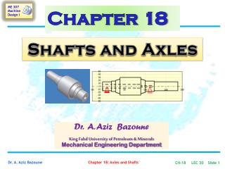
Chapter 18. Shafts and Axles. Dr. A. Aziz Bazoune King Fahd University of Petroleum & Minerals Mechanical Engineering Department. Chapter Outline.

E N D
Chapter 18 Shafts and Axles Dr. A. Aziz Bazoune King Fahd University of Petroleum & Minerals Mechanical Engineering Department
Chapter Outline 18-1 Introduction ……….92218-2 Geometric Constraints ……….92718-3 Strength Constraints ……….93318-4 Strength Constraints – Additional Methods ……….940 18-5 Shaft Materials ……….94418-6 Hollow Shafts ……….94418-7 Critical Speeds (Omitted) ……….94518-8 Shaft Design ……….950
LECTURE 30 18-1 Introduction ……….92218-2 Geometric Constraints ……….92718-3 Strength Constraints ……….933
Fatigue Analysis of shafts Neglecting axial loads because they are comparatively very small at critical locations where bending and torsion dominate. Remember the fluctuating stresses due to bending and torsion are given by Mm: Midrange bending moment, σm: Midrange bending stress Ma : alternating bending moment, σa: alternating bending stress Tm: Midrange torque, τm: Midrange shear stress Ta: alternating torque, τm: Midrange shear stress Kf: fatigue stress concentration factor for bending Kfs: fatigue stress concentration factor for torsion CH-18 LEC 30 Slide 4
Fatigue Analysis of shafts For solid shaft with round cross section, appropriate geometry terms can be introduced for C, I and J resulting in Mm: Midrange bending moment, σm: Midrange bending stress Ma : alternating bending moment, σa: alternating bending stress Tm: Midrange torque, τm: Midrange shear stress Ta: alternating torque, τm: Midrange shear stress Kf: fatigue stress concentration factor for bending Kfs: fatigue stress concentration factor for torsion CH-18 LEC 30 Slide 5
Fatigue Analysis of shafts Combining these stresses in accordance with the DE failure theory the von-Mises stress for rotating round, solid shaft, neglecting axial loads are given by (18-12) where A and B are defined by the radicals in Eq. (8-12) as The Gerber fatigue failure criterion CH-18 LEC 30 Slide 6
Fatigue Analysis of shafts The critical shaft diameter is given by (18-13) or, solving for 1/n, the factor of safety is given by (18-14) CH-18 LEC 30 Slide 7
Fatigue Analysis of shafts where (18-15) CH-18 LEC 30 Slide 8
Fatigue Analysis of shafts Particular Case For a rotating shaft with constant bending and torsion, the bending stress is completely reversed and the torsion is steady. Previous Equations can be simplified by setting Mm = 0 and Ta = 0, which simply drops out some of the terms. Critical Shaft Diameter (18-16) Safety Factor (18-17) CH-18 LEC 30 Slide 9
Fatigue Analysis of shafts (18-18) CH-18 LEC 30 Slide 10
Shaft Diameter Equation for the DE-Elliptic Criterion Remember (18-12) where A and B are defined by The Elliptic fatigue-failure criterion is defined by CH-18 LEC 30 Slide 11 CH-18 LEC 30 Slide 11
Shaft Diameter Equation for the DE-Elliptic Criterion Substituting for A and B gives expressions for d, 1/n and r: Critical Shaft Diameter (18-19) Safety Factor (18-20) CH-18 LEC 30 Slide 12
Shaft Diameter Equation for the DE-Elliptic Criterion CH-18 LEC 30 Slide 13
Shaft Diameter Equation for the DE-Elliptic Criterion Particular Case For a rotating shaft with constant bending and torsion, the bending stress is completely reversed and the torsion is steady. Previous Equations can be simplified by setting Mm = 0 and Ta = 0, which simply drops out some of the terms. Critical Shaft Diameter (18-21) Safety Factor (18-22) CH-18 LEC 30 Slide 14
Shaft Diameter Equation for the DE-Elliptic Criterion • At a shoulderFigs. A-15-8 and A-15-9 provide information about Kt and Kts. • For a hole in a solid shaft, Figs. A-15-10 and A-15-11 provide about Kt and Kts . • For a hole in a solid shaft, use Table A-16 • For grooves use Figs. A-15-14 and A-15-15 CH-18 LEC 30 Slide 15
Shaft Diameter Equation for the DE-Elliptic Criterion • The value of slope at which the load line intersects the junction of the failure curves is designated rcrit. • It tells whether the threat is from fatigue or first cycle yielding • If r > rcrit, the threat is from fatigue • If r < rcrit, the threat is from first cycle yielding. CH-18 LEC 30 Slide 16
Shaft Diameter Equation for the DE-Elliptic Criterion • For the Gerber-Langer intersection the strength components Sa and Sm are given in Table 7-10 as (18-23) CH-18 LEC 30 Slide 17
Shaft Diameter Equation for the DE-Elliptic Criterion • For the DE-Elliptic-Langer intersection the strength components Sa and Sm are given by (18-24) CH-18 LEC 30 Slide 18
Note that in an analysis situation in which the diameter is known and the factor of safety is desired, as an alternative to using the specialized equations above, it is always still valid to calculate the alternating and mid-rangestresses using the following Eqs. and substitute them into the one of the equations for the failure criteria , Eqs. (7-48) to (7-51) and solve directly for n. CH-18 LEC 30 Slide 19
In a design situation, however, having the equations pre-solved for diameter is quite helpful. • It is always necessary to consider the possibility of static failure in the first load cycle. • The Soderberg criteria inherently guards against yielding, as can be seen by noting that its failure curve is conservatively within the yield (Langer) line on Fig. 7–27, p. 348. • The ASME Elliptic also takes yielding into account, but is not entirely conservative throughout its range. This is evident by noting that it crosses the yield line in Fig. 7–27. • The Gerber and modified Goodman criteria do not guard against yielding, requiring a separate check for yielding. A von Mises maximum stress is calculated for this purpose.
To check for yielding, this von Mises maximum stress is compared to the yield strength, as usual • For a quick, conservative check, an estimate for σ’max can be obtained by simply adding σa and σm . (σa + σm ) will always be greater than or equal to σ’max, and will therefore be conservative. CH-18 LEC 30 Slide 23
Example Solution 7-20 7-20 CH-18 LEC 30 Slide 25
Figure 7-20 Figure 7-21 CH-18 LEC 30 Slide 26
18-22 Solderberg 18-14 18-24 CH-18 LEC 30 Slide 28