Download
1 / 33
330 likes | 393 Views
The Data Acquisition System for the K0TO Detector. Monica Tecchio University of Michigan on behalf of Myron Campbell, Shumin Li, Craig Harabedian , Jon Ameel University of Michigan Jiasen Ma, Yau Wah , Mircea Bogdan University of Chicago Joe Comfort, Duncan McFarland

E N D
The Data Acquisition Systemfor the K0TO Detector Monica Tecchio University of Michigan on behalf of Myron Campbell, Shumin Li, Craig Harabedian, Jon Ameel University of MichiganJiasen Ma, YauWah, MirceaBogdanUniversity of ChicagoJoe Comfort, Duncan McFarland Arizona State University Angela Steinmann Stetson University TIPP 2011 “Trigger and Data Acquisition Systems” Parallel Session Chicago, Sat. 11, 2011
K0TO Physics K0TO (K0 at Tokai)aims at discovering the FCNC KL p0nn • Forbidden at tree level BR(KL p0nn) = (2.43±0.39±0.06)x10-11 (PRD 83, 034030, 2011) • Dominated by heavy particle loops which can be calculated in perturbation theory at 2-3% • Direct CP violating process h2 (height of CKM unitarity triangle) CKM “Golden Mode”, very sensitive to new physics Present limits are: • From E391a @ KEK BR(KL0) < 2.6 x 10⁻⁸ (@ 90% CL) (PRD 81, 072004, 2010) • from E949 @BNL, which measured BR(K++) = (17.3 ± 11.0)x 10-11+ isospin symmetry relation (Grossman-Nir bound) (PRL 101, 191802, 2008)BR(KL0) < 1.5 x 10⁻⁹ (@ 90% CL)
KL Decay BR (E1,r1 ) collimator (E2,r2 ) 20 m Experimental Technique K0TO detects KL p0nndecays by looking for the two photons from the p0. Improves on experimental method pioneered by KEK-E391a. • Dedicated beam line for clean pencil-size KL beam to minimize halo particles and constrain KL decay vertex • High acceptance detector for photons, highly segmented to reconstructed separate clusters • Hermetic veto for photon and charged particles g Core photons Pb g proton KL X+p0 g B target g Core neutrons
K0TO Detector • KTeVCsI calorimeter (~3000 channels) plus charged/neutral vetos (~1000 channels) inside high vacuum pressure vessel • About 65 collaborators from 15 institutions (Japan, US, Korea, Russia, Taiwan) • Use 30-GeV Proton Synchrotron at J-PARC in Tokai, Japan • 2x10¹⁴ POT 8.1x10⁶ KL/spill • spill length/repetition time 0.7s/3.3s • <P(KL)> = 2.1 GeV/c for 16o extraction angle γ g
Huge background rates from KL p0p0require 1 MeV sensitivity for veto signal rejection. Also expected maximum photon energy deposition ~1.5 GeV. with 10 cnt/Mev, 14 bit dynamic range for energy measurement To minimize effect of accidental veto rejection, measure scintillation pulses with sub ns timing resolution. To reach SM sensitivity, need to detect as many KL p0nndecays as possible. Pipelined frontend and trigger to limit dead time To limit cost: Shape analog frontend signals and extract charge and time information with a single digitization. Build trigger and readout around these shaped signals. Physics Requirements
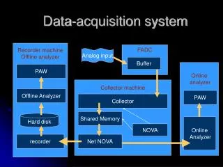
T&DAQArchitecture Readout Data PMT Analog Signals Clock & Controls
T&DAQ Architecture Computer farm for EVB and L3 software trigger. Readout Data PMT Analog Signals F1 ADC Trigger Two tier hardware Trigger. L1 energy sum threshold trigger L2 event-level trigger and readout interface. F2 ADC for frontend digitization and event pipelining. Receive Controls from Mactris. Send data to Trigger via separate output (F1 and F2). Clock & Controls Clock Master and Trigger Supervisor (MACTRIS)
Event Flow Digitized PMT Signal L1A Trigger SET • Input Pipeline (4 sec) on ADC: wait for L1 Trigger “K0TO Event” • ADC board ETSUMsent to L1 Trigger for L1A decision energy threshold • Upon L1 trigger, the event single channel energy is pushed out of L1 pipeline and sent to L2 Trigger L1A: First sampling with ESUM> ETHR Width: 40-64 samples
Event Flow Digitized PMT Signal L1A Trigger • Input Pipeline (4 sec) on ADC: wait for L1 Trigger L2A Trigger • ADC board ETSUMsent to L1 Trigger for L1A decision • Upon L1 trigger, the event single channel energy is pushed out of L1 pipeline and sent to L2 Trigger MEM 1 • L2 Trigger receives sequential events and for each issue a L2 accept/reject decision. ….. WRITE • Sequential L2A events are sent to one of two DDR2 2 Gbmemories. • Memories are alternatively in WRITE mode (for 0.7s spill) or READ mode (for 3.3s spill repetition time). ….. • With this scheme, we can reach 14 kHz L1 trigger rate (for 48 sampling trigger) with automatic L2A and no zero suppression. READ MEM 2
Event Flow • Readout is done over Gigabit Ethernet port via a switch. K0TO Event • switch redirects event fragments into a single PC L1A Trigger • while one PC is busy reconstructing the event, next trigger is sent to a different PC L1 pipeline L2A Trigger • reconstructed events are sent to storage Evt 1 Evt 2 .… Evt 16
Trigger and DAQ Block Diagram • 16x 6U VME frontend ADC crates with up to 16 modules each • 3x 9U VIPA Trigger Crates (CDF Trigger Crates, with P3 backplane) • Each board in a trigger crate services one full frontend crate • PC cluster farm with 40 nodes and 48-port switch • Modularity • Flexibility • Efficiency
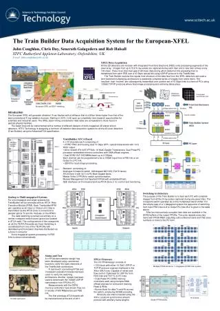
Trigger and DAQ Block Diagram Frontend ADC Crate
(see Jiasen Ma’s poster “A Pulse Shaping and Digitizing System with Subnanosecond Timing Resolution”) 6U VME board with fully pipelined dead-timeless design 16 analog inputs are shaped by 10-pole Gaussian filter taylored to PMT pulse characteristics resulting 45ns FWHM gaussian shape is digitized with 125MHz/14 bit FADC (110 ps resolution for 200 MeV) Controls are LVDS signals via CAT6 cable Two 2.5Gbs transceivers via optical fiber driver for signals to L1/L2 trigger peak t h Q After 10-pole filter PMT signal After digitization FADC Board
Trigger and DAQ Block Diagram MACTRIS Master Clock and Trigger Supervisor Board • oversees system integration • sits in L1 Trigger crate at the end of ETSUM daisy-chain • connects to each crate in the system Clock & Controls
MACTRIS Board DAQ Controls to L1/L2 • generate 8 ns system clock • generate system LIVE (beam gate defining t0) plus L1A decision using programmable logic (on-board FPGA) • receive daisy-chained ETSUM from J3 backplane connector • distribute Controls (clk, LIVE, L1A) as LVDS to ADC via RJ45 front panel port • distribute clock and DAQ Controls to L1 and L2 crates via 68-pin front panel connector and inject them into P2 backplane (Slave Mactris) • provide interface to accelerator signals via NIM/LVDS front panel ports clock FPGA J2 Accelator Controls J3 Controls to ADC
Trigger and DAQ Block Diagram Fanout Crate
Fanout Board Controls to ADCs 1-to-16 Repeater board for Controls from Mactris to one ADC Crate Four LVDS Controls: 3 outputs (clk, t0 and L1A), one input (ERROR) • receives master copy via front panel RJ45 • generates 16 copies to ADCs via front panel RJ45 Used in cascade: Master Fanout to 16 Slave Fanouts to 16 frontend Crates Controls from MACTRIS
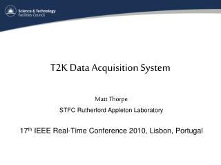
Trigger and DAQ Block Diagram L1 Trigger Crate • up to 12 x L1 Trigger Boards • P3 backplane with ETSUM daisy-chain
L1 Trigger Board 16 L1 Fiber inputs • 16x2.5Gbs optical fiber inputs to SERDES (Texas TLK3101) • DAQ Controls via J2 connector or front-panel RJ45 connector • Etsum daisy-chain via J3 backplane • Xilinx Virtex5 FPGA: • align energy of 16 input fibers to system clock • generate ETSUM for full ADC crate • Align local ETSUM to ETSUM from daisy-chain • VME Interface • Clock and data bus routing are critical to avoid TLK loss-of-sync SERDES (TLK3101) J2 RJ45 J3 Virtex 5 FPGA
Trigger and DAQ Block Diagram L2 Trigger Crate • up to 16 x L2 Trigger Boards
L2 Trigger Board DDR2 Memories Same layout as L1 Trigger board. Unlike L1 Trigger board, it also uses: • Xilinx Virtex 4 FPGA (slave) connected to Virtex 5 FPGA (master) via 32-bit data bus • 2x 2Gb DDR2 memories • Ethernet PHY and 1Gb Ethernet port to PC Farm • Virtex5 FPGA: • store ADC energy after each trigger into 16K deep FIFOs • multiplex input fiber energy onto 32-bit bus • event gaussian fit logic • Virtex4 FPGA: • host DDR2 memory interface • host Ethernet MAC interface • build Standard/JUMBO Ethernet packets using IP/UDP protocol Ethernet PHY Slave FPGA 1 Gb port Master FPGA
Trigger and DAQ Block Diagram EVB and Readout Farm
Readout Farm (Mandolin) Provides offline reconstruction, online monitoring and temporary data storage • 41 Dell PowerEdge SC1435 servers (1 Head, 40 Clients) • 2 dual-core AMD Opteron 2.6-GHz processors each • 16 GB memory • two 1Gb Ethernet NIC cards • 250-GB system disk and 750-GB data disk each • 48 port Dell Power Connect Layer 3 switch • up to 184 Gb/s capacity • four 10 GB ports • Event fragments from N consecutive triggers will be routed to N separate PCs (N=16)
K0TO T&DAQ Status 3000 channels of calorimeter readout (frontend and trigger) are completed and either delivered to Japan or under test at University of Michigan. MC simulation requires some minimal veto trigger to keep L1 trigger rates at 120 KHz for 300 MeVEtSUM threshold (assuming final KL yield) Veto channels production • majority will be digitized by the same 125 MHz ADC boards • ~100 channels of beam hole photon veto (BHPV) will use 12-bit/500 MHz digitization of unshaped PMT signal. Board Design ready. Waiting for funding • L1 Trigger board under design. Waiting for funding. • L2 Trigger/Readout board common to whole system. FPGA and software under development.
T&DAQ Tests 12x12 calorimeter channel beam tests were done at LNS Electron/Photon beam in 2010: • check of analog readout performance • test of trigger/DAQ chain with prototype boards 800 MeV event PRELIMINARY Gaussian height calibration (cnt/MeV) Cosmic event
T&DAQ Tests Partial (~1800 Csi crystals) calorimeter test was done in JPARC using final beam line in Dec. 2010 (with upstream tracking chambers in magnetic field) • ADCs readout via VME to Mandolin cluster • ETSUM trigger using 90 channels • reconstructed KL mass from KL p+p-p0and KL p0p0p0 decays
Schedule • Before March 11 Earthquake, schedule had full detector run in Dec. 2011, followed by physics run aiming to reach GN limit in Spring 2012 • Earthquake/tsunami created no major visible damage to accelerator or KL beam line or K0TO detector. Tests still under way. • On May 20th, JPARC posted a recovery plan with the goals of: • start beam commissioning in Dec. 2011, with beam injection to confirm facility recovery • restart user program with beam time of about 50 days before end of March 2012 For latest status, see http://j-parc.jp/en/topics/2011/en.html#Status0531 • As a result, first K0TO Physics run pushed back by about 1 year
Summary • K0TO experiment is to discoverKL p0nn • New Trigger & DAQ built to comply with physics requirements of: • pipelined readout and trigger electronics with no deadtime • 14-bit dynamic range on the energy measurement • time resolution of 0.5 nsec • New beamline at JPARC 30 GeV proton accelarator plus upgraded detector ready to take data by end of 2012
The Data Acquisition Systemfor the K0TO Detector Backups TIPP 2011 “Trigger and Data Acquisition Systems” Parallel Session Chicago, Sat. 11, 2011
KL Decay BR core photon, neutron g proton KL target collimator g What does it take to catch a KL p0nn ? • Clean KL beam • High Acceptance Detector • KL p0nnis detected viap0 plus “nothing” • need thick finely-grained calorimeter • Any other KL decay has either no pT or extra photon/charged particle Monica Tecchio
(E1,r1 ) g q p0 g (E2,r2 ) KL p0nn Reconstruction Fully reconstruct KLp0nnkinematics • calorimeter gives energy and position • by constraining 2 system to mass, get the two photon opening angle • assuming KL decay vertex on beam line, determine Zvtx of decay NB: E 1/while m
PT signal region p+p-p0 p0p0 (even) KL→2π0 p0nn KL→π+π-π0 Zvtx KL→2γ Signal Region KL p0nn Reconstruction Identify kaon backgrounds • define signal box in p0 PT-Zvtx using: • fiduciality cuts for Zvtx • PT above K3 threshold and above (V-A) maximum of 231 MeV/c • no activity in vetoes • kaon decays w/w.o. particles escaping detection: • low PT or Z shifted upstream • have unphysical (E-) relation • larger 2energy ratio • fused clusters with wrong e.m. shower profile
Basic experimental method is sound: BR < 2.6x10⁻⁸ (at 90%CL). Need to improve x103! Improvements over E391a Monica Tecchio