Download
1 / 42
420 likes | 430 Views
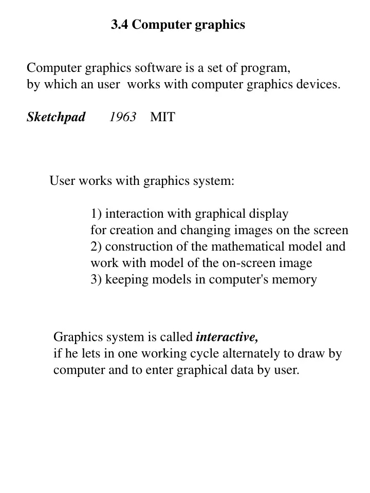
3.4 Computer graphics. Computer graphics software is a set of program , by which an user works with computer graphics devices. Sketchpad 1963 MIT. User works with graphics system : 1) interaction with graphical display for creation and changing images on the screen

E N D
3.4 Computer graphics Computer graphicssoftware is a set of program, by which an user works with computer graphics devices. Sketchpad 1963MIT User works with graphics system: 1) interaction with graphical display for creation and changing images on the screen 2)construction of the mathematical model and work with model of the on-screen image 3)keeping models in computer's memory Graphics system is called interactive, if he lets in one working cycle alternately to draw by computer and to entergraphical data by user.
Designers workplace Graphical display Graphics package Application DB Application program package Graphical I/O devices Computer graphics - software Windows on the screen
Shaft sketch CONE SHAFT CYLINDER AT 10,80 LINE 0,-20,0,20 LINE 0,-20,0,20 CYLINDER LINE 0,20,70,20 LINE0,20,40,10 AT 80,120 LINE 70,20,70,-20 LINE 40,10,40,-10 CONE LINE 70,-20,0,-20 LINE 40,-10,0,-20 END END END Data structures for drawing a shaft
DEFINE SHAFT LINE FROM (10.0)TO(10,20)TO(80,20)TO(120,10) TO(120,-10)TO(80,-20)TO(10,-20)TO(10,0) LINE FROM(80,20)TO(80,-20) END SHAFT
CADS KymData Ky CADS ... KUVAT SMBT TYOH 4 diskettesor CD A:<enter> CINSTALL<enter> CONFIG.SYS FILES=30 BUFFERS=20 + protection module §1 OS manual §2 Start CADS v. 5.20 *aloitusmenu * ................ Kuvan nimi ? (Drawing name?) F1:Asetukset F2:Tulostus F3:Help F4:Poisto F5:Dok Settings Plotting Remove Doc
CADS * parameters * Parameter to be changed?_ Q...Default text size 5.00 mm R...Raster division 5.00 mm Y...Fillet radius 10.00 mm N...Arrow length 5.00 mm A...Arrow angle 15.000 T...Raster display Yes D...Coordinate system x-y coord. System M...Automatic dimens. Yes I...Dimensioning type Machine drawing U...Screen menu Yes L...Menu field width 8 K...Two instr. Lines Yes F3:help F7:exit
F1 settings - süsteemi ettevalmistus ja koef. valik F2 plotting - piltide väljastamise režiim F3 help - lühiinfo F4 remove - pildi kustutamine F5 document - pildile lisatava dokumendi sisu F7 end - CADS seansi lõpp RETURN drawing directory – antakse piltide (jooniste) nimed RETURN editing - redig. jooksvat või uut pilti CADS *settings * (c) KymData Ky Select setting function?_ K...Drawing directory path \KUVAT\ S...Symbol directory path \SMBT\ T...Working directory path \TYOT\ I...Editor name Pedit A...Drawing area size x:380.0 Y:250.0 M...Drawing scale 1:1.0 L...Input Device TABLET P...Plotter type HP7475 R...Plotter line COM2 N...Graphics card O... X... ... F1 parameters F3:help F7:exit
Basics of drawing Cursor Mouse Graphic board (digitaizer) Selection of operations: a) from keyboard 3 characters VVA b) move the cursor to the menu, make a click with mouse (mouse button) c) choose operation from graphic board menu Main operations: - VVA line drawing - JVA continuous line - KAA arc-drawing ... - MOK drawing a polygon Texts - TXT text - TXK text size
Treatment of symbols Treatment of domains Levels of the picture Zoom PadLan language
Actual problems ofCAD Ahto Kalja
1. Formal design methods for CAD - Tallinn 1993 - Mexico City 1995 2. Artificial Intelligence in Design ‘94 - Lausanne AID’96 - Stanford AID´98 - Lisbon AID´00 3.Design Computing E-Newsletter’s No 1-29
Actual problems of CAD • CONCEPTUAL DESIGN, MODELS ANDLANGUAGES • KNOWLEDGE AND DATA REPRESENTATION IN CAD • MACHINE LEARNING IN CAD • CONCURRENT ENGINEERING, RESOLVING CONFLICTS • CASE-BASED DESIGN SYSTEMS • CONSTRAINT PROCESSING IN CAD • THEORETICAL REASONING IN DESIGN • DESIGN BY GENERATION • SHAPES AND OBJECTS IN DESIGN • GREATIVE DESIGN, EXPLORATION IN CAD • AGENTS AND WEB-BASEDDESIGNENVIRONMENTS
1. Conceptual Design ...as that part of the design process in which: problems are identified, functions and specifications are laid out and appropriate solutions are generated through the combination of some basic blocks. Conceptual design, unlike analysis, has no fixed procedure and involves a mix of numerix and symbolic reasoning. (Navinchandra, 1992). Conceptual design includethree groups of operations: A: GENERATE: select, create B: EVALUATE: simulate,calculate, compare C: DECIDE: accept, reject, suspend, refine, patch Synthesis: synthetic processes act to combine elements of design information into new models Analysis:using case-based reasoning or classification in design decision-making activities
Categorization of desing process models • descriptive model=explains how design is done • cognitive model=explains the designer’s behavior (thinking process) • prescriptive model=show how design should be done • computational model=expresses a method by which a computer can accomplish the design task knowledge This formula works if you know R Execution phaseof design R U K S solution requirements S U K P Development phaseof design Set of properties P<=>R Comparison of sets of properties Analogies between language and design LanguageDesign Vocabularywordsparts Syntaxgrammar actions for configuration Uttarancessentencesdesigns Semanticsmeaninginterpretation of designs as performances
Prototypes model * Is based on object-oriented paradigma * Investigates: - inheritance between design objects - generation of the new prototype variants new design objects as well * Used languages: CLOS, C++, Smalltalk Ellectrical prop. -nominal voltage: -nom. frequency: ... Physical prop. - weight: - heigth: ... Environmental p. -operating temp.: -air flow: ... Product Three viewpoints an electro-mechanical product
2. Representation of knowledge and data Specification of design task Knowledge Solutions Inference engines bases *PRIZ-NUT type problem solvers *PROLOG and extensions *Inductive type Expert system shells *Interactive graphics processors *DBMS-s ... ... Databases ...
Development of AI based software systems(in CAD related areas) • Frame-based languages Quillion 1966, M. Minsky KL-One, NETL, FRL, Units, KRL, KEE, SRL 84 B. Common Lisp J. McCarthy 1956-58 MIT, only Fortran language is older Franz Lisp, Interlisp, MacLisp,… - efficiency is high for Common Lisp compilers today, works good in mixed mode (interp. and comp.) as well - control structuresin addition to COND and GOTO exist a large set of conditionaloper., iterations (for lists) etc. - data typesration. numbers, floating-point numbers, complex numbers, vectors, arrays, records, files,… - libraries70 + 40 different f –nslists oper. - typecontroldynamic and static - parameters list pos. parameters + keywords +fakt. param. - on-line documentation
Lisp programing environments editors, Emacs, • interaktive interpretators debuggers included- parallel processing C Natural language processing As old as AI Hot topic is natuaral language interfaces (english). A good example is Language Craft. It is using “case frame grammar”. Case frame parser is using a large number of language constructions etc. D Prolog Good for prototyping CPE
Opening of the problem Prob. defin./Realization of probl. Change Specification of subtasks Change Specification of concepts Change Conceptual design Change Detailed design Change Coding Change Software testing Change Change the structure Knowledge testing Change the structure Change Evaluation Change Maintenance/extension New problems Developing software systems with knowledge bases
Selected problem Feasibility of the problem Knowledge accession Interim results presentation Evaluation with an expert Knowledge present. in KB Evaluation with an expert End if costs exceed significance of the results Maintenance, appraisal rep. Life cycle of expert system
3. Machine learning in design Machine learning task is to identify andsave old projects specificcharacteristic and accurate knowledge. Problems to be solve : • What is the benefit of machine learning opportunities for solving design problems? • Which facilities of machine learning should be develop for solving design problem? • Which are restrictions? ... Machine learning benefits: • a better understanding will appear: how todesign; • shows what kind of important decisions to make and when; • shows what factors are important for decisions making; • showss how these decisions follows as features of product; • arises reusable knowledge of good production and technological opportunities; • arises re-user experience about market situation; • etc.
4. Concurrent engineering, resolving conflicts Concurrent engineering is an approach to design which takes into account not just the functionality of a product but also its manufacturability, testability, and aspects from business such as finance, cash flow analyses and marketing. Concurrent engineering requires cooperation among many experts from various disciplines who are involved at various states of the product life cycle. Negotiation protocol should provide the following support to the team: • Collection of client preferences; • Detection of situations of potential conflictbetween design decisions, • Collection of compromise solutions; • Evaluation based on the client preferences ofthose solutions; and • Output of the best solution to the clients for itsexecution.
5. Case Based Reasoning in Design M1 r1 l2 E1 a b l1 tri P1 T1 Annotation + - Using oil MS-6 causes additional system weigth 11.8% and volume increasing 6.3%
Past research on CBR focused a number of issues: • What information should the case contain? (pertaining problem) * How should the case memory be organized &where new case should be placed? (comprehension problem) * What method should be used to retrieve cases from the case memory...(indexing problem) • How can a stereotyped retrieved solution be adapted to the new context of the designed problem? (adapting problem) * How can cases be acquired from the domain experts and put in the case memory? More actual problems: • how present and modify libraries of graphic cases? • how to organize search between graphic cases? • how to use Internet for developing and using graphic cases? • how to develop and use case libraries in multi users situation
DESIGN BY GENERATION This example uses five grammar rules: 1)S->lbs Li ls Ri rbs 2)Li->sli 3)Li->sli Lj 4)Ri->sri 5)Ri->sri Rj
Conclusions • Creation of knowledge bases and inference enginesremains a very important area in CAD.Mainstream is the creation of distributed systems. • One novel direction is connecting interactive computer graphics withknowledgebases. • OO-programming paradigm has lost its novelty. • The analysis stage is now overwhelming case-based reasoning methods. His current focus is the using of multimedia, and the using of graphical data-know- ledgeorganization. • Modelling design as a thinking process has got fast development. • Using Internet as a design environment expands everywhere.