Download
1 / 35
350 likes | 515 Views
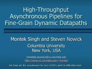
High-Throughput Asynchronous Pipelines for Fine-Grain Dynamic Datapaths. Montek Singh and Steven Nowick Columbia University New York, USA {montek,nowick}@cs.columbia.edu http://www.cs.columbia.edu/~montek.

E N D
High-ThroughputAsynchronous Pipelines forFine-Grain Dynamic Datapaths Montek Singh and Steven Nowick Columbia University New York, USA {montek,nowick}@cs.columbia.edu http://www.cs.columbia.edu/~montek Intl. Symp. Adv. Res. Asynchronous Circ. Syst. (ASYNC), April 2-6, 2000, Eilat, Israel.
Outline • Introduction • Background: Williams’ PS0 pipelines • New Pipeline Designs • Dual-Rail: LP3/1, LP2/2 and LP2/1 • Single-Rail: LPSR2/1 • Practical Issue: Handling slow environments • Results and Conclusions
Why Dynamic Logic? Potentially: • Higher speed • Smaller area • “Latch-free” pipelines: Logic gate itself provides an implicit latch • lower latency • shorter cycle time • smaller area –– very important in gate-level pipelining! • Our Focus:Dynamic logic pipelines
How Do We Achieve High Throughput? • Introduce novel pipeline protocols: • specifically target dynamic logic • reduce impact of handshaking delays • shorter cycle times • Pipeline at very fine granularity: • “gate-level:” each stage is a single-gate deep • highest throughputs possible • latch-free datapaths especially desirable • dynamic logic is a natural match
Prior Work: Asynchronous Pipelines • Sutherland (1989), Yun/Beerel/Arceo (1996) • very elegant 2-phase control expensive transition latches • Day/Woods (1995), Furber/Liu (1996) • 4-phase control simpler latches, but complex controllers • Kol/Ginosar (1997) • double latches greater concurrency, but area-expensive • Molnar et al. (1997-99) Two designs: asp* and micropipeline both very fast, but: • asp*: complex timing, cannot handle latch-free dynamic datapaths • micropipeline: area-expensive, cannot do logic processing at all! • Williams (1991), Martin (1997) • dynamic stages no explicit latches! low latency • throughput still limited
Background • Introduction • Background: Williams’ PS0 pipelines • New Pipeline Designs • Dual-Rail: LP3/1, LP2/2 and LP2/1 • Single-Rail: LPSR2/1 • Practical Issue: Handling slow environments • Results and Conclusions
PC Data in Data out Function Block Completion Detector PS0 Pipelines (Williams 1986-91) Basic Architecture:
to completion detector PC “keeper” precharge control datainputs Pull-down stack dataoutputs evaluation control PS0 Function Block Each output is produced using a dynamic gate:
bit0 bit1 bitn OR OR OR Done C Dual-Rail Completion Detector • OR together two rails of each bit • Combine results using C-element
4 3 N+1 indicates “done” 6 5 1 2 3 PS0 Protocol • PRECHARGE N: when N+1 completes evaluation • EVALUATE N: when N+1 completes precharging N+2 indicates “done” N+1 indicates “done” N N+1 N+2 N+1 precharges N evaluates N+1 evaluates N+2 evaluates Complete cycle: 6 events Evaluate Precharge: 3 events Precharge Evaluate: another 3 events
6 4 Cycle Time = 5 1 2 3 PS0 Performance
New Pipeline Designs • Introduction • Background: Williams’ PS0 pipelines • New Pipeline Designs • Dual-Rail: LP3/1, LP2/2 and LP2/1 • Single-Rail: LPSR2/1 • Practical Issue: Handling slow environments • Results and Conclusions
Overview of Approach Our Goal: Shorter cycle time, without degrading latency Our Approach: Use “Lookahead Protocols” (LP): • main idea: anticipate critical events based on richer observation Two new protocol optimizations: • “Early evaluation:” • give stage head-start on evaluation by observing events further down the pipeline (actually, a similar idea proposed by Williams in PA0,but our designs exploit it much better) • “Early done:” • stage signals “done” when it is about to precharge/evaluate
PC Eval N N+1 N+2 Data in Data out From N+2 Dual-Rail Design #1: LP3/1 Uses “early evaluation:” • each stage now has two control inputs • the new input comes from two stages ahead • evaluate N as soon as N+1 starts precharging
New! 3 4 N+1 indicates “done” 3 1 2 Enables “early evaluation!” LP3/1 Protocol • PRECHARGE N: when N+1 completes evaluation • EVALUATE N: when N+2 completes evaluation N+2 indicates “done” N N+1 N+2 N+2 evaluates N evaluates N+1 evaluates
4 5 4 6 1 2 3 3 1 2 LP3/1: Comparison with PS0 N N+1 N+2 LP3/1 Only 4 events in cycle! N N+1 N+2 PS0 6 events in cycle
4 3 1 2 Cycle Time = LP3/1 Performance saved path Savings over PS0:1 Precharge + 1 Completion Detection
PC (From Stage N+1) Eval (From Stage N+2) NAND “keeper” Pull-down stack Inside a Stage: Merging Two Controls A NAND gate combinesthe two control inputs: • Precharge when PC=1(and Eval=0) • Evaluate “early” when Eval=1(or PC=0) • Problem:“early”Eval=1 is non-persistent! • it may get de-asserted before the stage has completed evaluation!
PC (From Stage N+1) Eval (From Stage N+2) NAND LP3/1 Timing Constraints: Example Problem:“early”Eval=1 is non-persistent! Observation:PC=0soon afterEval=1, and is persistent use PC as safe “takeover” for Eval! Solution: no change! Timing Constraint:PC=0 arrives beforeEval=1 is de-asserted • simple one-sided timing requirement • other constraints as well… all easily satisfied in practice
Data in Data out Function Block “early” Completion Detector Dual-Rail Design #2: LP2/2 Uses “early done:” • completion detector now beforefunctional block • stage indicates “done” when about to precharge/evaluate
PC bit0 bitn bit1 OR OR OR Done C + + + LP2/2 Completion Detector Modified completion detectors needed: • Done=1 when stage starts evaluating, and inputs valid • Done=0 when stage starts precharging • asymmetric C-element
N+1 “early done” N+1 “early done” 2 3 4 N+2 “early done” 1 2 3 LP2/2 Protocol Completion detection occurs in parallel with evaluation/precharge: N N+1 N+2 N evaluates N+1 evaluates
3 Cycle Time = LP2/2 Performance 4 1 2 LP2/2 savings over PS0: 1 Evaluation + 1 Precharge
Cycle Time = Dual-Rail Design #3: LP2/1 Hybrid of LP3/1 and LP2/2. Combines: • early evaluation of LP3/1 • early done of LP2/2
New Pipeline Designs • Introduction • Background: Williams’ PS0 pipelines • New Pipeline Designs • Dual-Rail: LP3/1, LP2/2 and LP2/1 • Single-Rail: LPSR2/1 • Practical Issue: Handling slow environments • Results and Conclusions
delay delay delay • “Ack” to previous stages is “tapped off early” • once in evaluate (precharge), dynamic logic insensitive to input changes Single-Rail Design: LPSR2/1 Derivative of LP2/1, adapted to single-rail: • bundled-data: matched delays instead of completion detectors
PC (From Stage N+1) Eval (From Stage N+2) matcheddelay “ack” NAND “req” out done “req” in data out data in aC + • “done” generated by an asymmetric C-element • done=1 when stage evaluates, and data inputs valid • done=0 when stage precharges PC and Eval are combined exactly as in LP3/1 Inside an LPSR2/1 Stage
N+1 indicates “done” N+2 indicates “done” 2 3 2 1 N+1 evaluates N+2 evaluates Cycle Time = LPSR2/1 Protocol N N+1 N+2 N evaluates
Practical Issue: Handling Slow Environments We inherit a timing assumption from Williams’ PS0: • Input (left) environment must precharge reasonably fast Problem: If environment is stuck in precharge, all pipelines (incl. PS0) will malfunction! Our Solution: • Add a special robust controller for 1st stage • simply synchronizes input environment and pipeline • delay critical events until environment has finished precharge • Modular solution overcomes shortcoming of Williams’ PS0 • No serious throughput overhead • real bottleneck is the slow environment!
Results and Conclusions • Introduction • Background: Williams’ PS0 pipelines • New Pipeline Designs • Dual-Rail: LP3/1, LP2/2 and LP2/1 • Single-Rail: LPSR2/1 • Practical Issue: Handling slow environments • Results and Conclusions
Results Designed/simulated FIFO’s for each pipeline style Experimental Setup: • design: 4-bit wide, 10-stage FIFO • technology: 0.6 HP CMOS • operating conditions: 3.3 V and 300°K
Comparison with Williams’ PS0 • LP2/1:>2X faster than Williams’ PS0 • LPSR2/1:1.2 Giga items/sec dual-rail single-rail
Comparison: LPSR2/1 vs. Molnar FIFO’s LPSR2/1 FIFO: 1.2 Giga items/sec Adding logic processing to FIFO: • simply fold logic into dynamic gate little overhead Comparison with Molnar FIFO’s: • asp* FIFO: 1.1 Giga items/sec • more complex timing assumptions not easily formalized • requires explicit latches, separate from logic! • adding logic processing between stages significant overhead • micropipeline: 1.7 Giga items/sec • two parallel FIFO’s, each only 0.85 Giga/sec • very expensive transition latches • cannot add logic processing to FIFO!
fan-out=2 done comp. det. fan-in = 2 datapath width = 32 dual-rail bits! Practicality of Gate-Level Pipelining When datapath is wide: • Can often split into narrow “streams” • Use “localized” completion detector for each stream: • need to examine only a few bits small fan-in • send “done” to only a few gates small fan-out • comp. det. fairly low cost!
Conclusions Introduced several new dynamic pipelines: • Use two novel protocols: • “early evaluation” • “early done” • Especially suitable for fine-grain (gate-level) pipelining • Very high throughputs obtained: • dual-rail:>2X improvement over Williams’ PS0 • single-rail:1.2 Giga items/second in 0.6 CMOS • Use easy-to-satisfy, one-sided timing constraints • Robustly handle arbitrary-speed environments • overcome a major shortcoming of Williams’ PS0 pipelines Recent Improvement: Even faster single-rail pipeline (WVLSI’00)