Download
1 / 96
960 likes | 976 Views
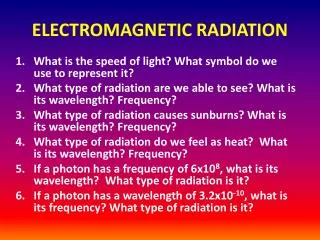
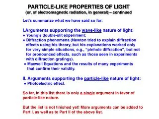
Chapter 1 General Properties of Electromagnetic Radiation.

E N D
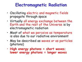
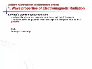
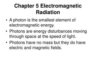
The electromagnetic radiation is looked at as sinusoidal waves which are composed of a combination of two fields. An electric field (which we will use, in this course, to explain absorption and emission of radiation by analytes) and a magnetic field at right angle to the electric field (which will be used to explain phenomena like nuclear magnetic resonance in the course of special topics in analytical chemistry offered to Chemistry students only).
The classical wave model The classical wave model describes electromagnetic radiation as waves that have a wavelength, frequency, velocity, and amplitude. These properties of electromagnetic radiation can explain classical characteristics of electromagnetic radiation like reflection, refraction, diffraction, interference, etc. However, the wave model can not explain the phenomena of absorption and emission of radiation.
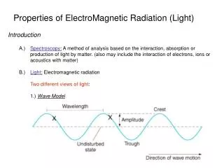
We will only deal with the electric field of the electromagnetic radiation and will thus refer to an electromagnetic wave as an electric field having the shape of a sinusoidal wave. The arrows in the figure below represent few electric vectors while the yellow solid sinusoidal wave is the magnetic field associated with the electric field of the wave.
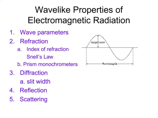
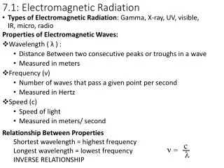
Wave Parameters 1. Wavelength () The wavelength of a wave is the distance between two consecutive maxima or two consecutive minima on the wave. It can also be defined as the distance between two equivalent points on two successive maxima or minima. This can be seen on the figure below:
2. Amplitude (A) The amplitude of the wave is represented by the length of the electrical vector at a maximum or minimum in the wave. In the figure above, the amplitude is the length of any of the vertical arrows perpendicular to the direction of propagation of the wave.
The frequency of the wave is directly proportional to the energy of the wave and is defined as the number of wavelengths passing a fixed point in space in one second. 3. Frequency 4. Period (p)الفترة The period of the wave is the time in seconds required for one wavelength to pass a fixed point in space.
5. Velocity (v) The velocity of a wave is defined as the multiplication of the frequency times the wavelength. This means: V = The velocity of light in vacuum is greater than its velocity in any other medium
Since the frequency of the wave is a constant and is a property of the source, the decrease in velocity of electromagnetic radiation in media other than vacuum should thus be attributed to a decrease in the wavelength of radiation upon passage through that medium.
- 6. Wavenumber (): مقلوب الطول الموجي The reciprocal of wavelength (1/)in centimeters is called the wavenumber. This is an important property especially in the study of infrared spectroscopy. Wavenumber is directly proportional to frequency and thus E • = k k depends on medium and = 1/velocity -
Electromagnetic Spectrum The electromagnetic radiation covers a vast شاسع spectrum of frequencies and wavelengths. This includes the very energetic gamma-rays radiation with a wavelength range from 0.005 – 1.4 Aoto radio waves in the wavelength range up to meters (exceedingly low energy). However, the region of interest to us in this course is rather a very limited range from 180-780 nm. This limited range covers both ultraviolet and visible radiation.
Mathematical Description of a Wave A sine wave can be mathematically represented by the equation: Y = A sin (t + ) Where y is the electric vector at time t, A is the amplitude of the wave, is the angular frequency, and is the phase angle of the wave (زاوية بداية الموجة). The angular frequency is related to the frequency of radiation by the relation: = 2 This makes the wave equation become: Y = A sin (2t + )
Mathematic Description of a Wave w = angular frequency = 2pn = Y = A sin(2t + f), n is the regular frequency Douglas A. Skoog, et al. Principles of Instrumental Analysis, Thomson, 2007
Superposition of Wavesتراكب الأمواج When two or more waves traverse تعبر the same space, a resultant wave, which is the sum of all waves, results. Where the resultant wave can be written as: Y = A1 sin (21t+ 1) + A2 sin (2t + ) + ........ + An sin (2nt+ n)
Optical Interference: The interaction of two or more light waves yielding an irradiance that is not equal to the sum of the irradiances.
Constructive Interference The resultant wave would has a greater amplitude than any of the individual waves which, in this case, is referred to as constructive interference. The opposite could also take place where lower amplitude is obtained. When the multiple waves have the same wavelength, maximum constructive interference takes place when 1 - 2 is equal to zero, 360 deg or multiple of 360 deg.
Constructive Interference 1) Have identical frequency 2)f2 – f1 = d = m2p f2 – f1 = 0, or 360 deg or integer of multiple of 360 deg. ie start with each others or by integer of 360 (mX360)
Constructive Interference A 100% constructive interference can be seen for interference of yellow and blue shaded waves resulting in a wave of greater amplitude, brown shaded.
destructive Interference The decrease in the intensity is a result of what is called a destructive interference. Maximum destructive interference is observed when 1 – 2 is equal to 180 deg, or 180 deg + multiples of 360 deg.
Destructive Interference 1) Have identical frequency 2)f2 – f1 = d = (2m+1)p f2 – f1 = 180 deg or integer of multiple of 360 deg + 180 deg.
The blue and yellow shaded waves interfere to give the brown shaded wave of less amplitude, a consequence of destructive interference of the two waves.
Superposition of sinusoidal wave: (a) A1 < A2, (1 - 2) = 20º, 1 = 2; (b) A1 < A2, (1 - 2) = 200º, 1 = 2
The Period of a Beat When two waves of the same amplitude but different frequencies interfere, the resulting wave exhibit a periodicity and is referred to as beat (see figure below). The period of the beat can be defined as the reciprocal of the frequency difference between the two waves: Pb = 1/()
The time in seconds required for one beat to pass a fixed point in space.
Should be Superposition of two sinusoidal wave of different frequencies but identical amplitudes.
Fourier Transform The resultant wave of multiple waves of different amplitudes and frequencies can be resolved back to its component waves by a mathematical process called Fourier transformation. This mathematical technique is the basis of several instrumental techniques like Fourier transform infrared, Fourier transform nuclear magnetic resonance, etc.
Diffraction of Radiation Diffraction is a characteristic of electromagnetic radiation. Diffraction is a process by which a parallel beam of radiation is bent when passing through a narrow opening or a pinholeفتحة صغيرة جدا . Therefore, diffraction of radiation demonstrate تثبت its wave nature. Diffraction is not clear when the opening is large.
Diffraction Pattern From Multiple Slits CF = BC sin = n n is an integer called order of interference as BD =FD So the type of interferences depend on the value of CF in number of : If CF is integer number of (Constructive) If CF is (integers + fractions number of (Destructive) اذا كان الفرق في الطور يساوي صفر : بناء (مضيئة) واذا كان الفرق عدد صحيح من الاطوال الموجية + 180 في الطور يكون هدام (معتمة)
تساوق-تماسك Coherence of Radiationto give diffraction patterns Two beams من فتحتينof radiation are said to be coherent if they satisfy the following conditions: 1. Both have the same frequency and wavelength or set of frequencies and wavelength. 2. Both have the same phase angle relationships with time. 3. Both are continuous (W lamp) .
Transmission of Radiation As mentioned before, the velocity of radiation in any medium is less than that in vacuum. The velocity of radiation is therefore a function of the refractive index of the medium in which it propagates. The velocity of radiation in any medium can be related to the speed of radiation in vacuum ( c ) by the relation: ni = c/vi (>1). Where, viis the velocity of radiation in the medium i, and ni is the refractive index of medium i.
The decrease in radiation velocity upon propagation in transparent media is attributed to periodic polarization of atomic and molecular species making up the medium. By polarization we simply mean temporary induced deformation of the electronic clouds of atoms and molecules as a result of interaction with electric field of the waves.
Dispersion تشتت - تفكك of Radiation If we look carefully at the equation ni = c/viand remember that the speed of radiation in vacuum is constant and independent on wavelength, and since the velocity of radiation in medium i is dependent on wavelength, therefore the refractive index of a substance should be dependent on wavelength.The variation of the refractive index with wavelength is called dispersion.
There is a change of wavelength with change of RI (eg Prisms) No change of wavelength with change of RI (eg lenses, windows)
1 3 2 : angle of deviation A ray of single-wavelength incident on a prism
A ray of white-wavelength incident on a prism R B White light
Refraction of Radiation When a beam of radiation hits the interface between two transparent media that have different refractive indices, the beam suffers an abrupt changeتغير مفاجئ in direction or refraction. The degree of refraction is quantitatively shown by Snell's law where: n1 sin 1 = n2 sin 2
Reflection of Radiation An incident beam hitting transparent surfaces (at right angles) with a different refractive index will suffer successive reflections. This means that the intensity of emerging beam will always be less than the incident beam. About 8.5% of the incident beam is lost.