Download
1 / 23
270 likes | 426 Views
Fluoroscopy: Viewing Systems. TV Monitors. Video CRT Monitor. A video monitor (television tube) is a cathode ray tube (CRT). Consists of:. TV Monitor. Cable. A vacuum tube. Electron gun as part of cathode at back of tube. www.kentmusictechnology.co.uk. External coils

E N D
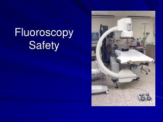
Fluoroscopy: Viewing Systems TV Monitors
Video CRT Monitor A video monitor (television tube) is a cathode ray tube (CRT) Consists of: TV Monitor Cable A vacuum tube Electron gun as part of cathode at back of tube www.kentmusictechnology.co.uk External coils for focusing and steering electron beam Fluorescent phosphor coating inside front screen Anode plated onto front screen Video signal Video signal is amplified and transmitted by cable to the television monitor It is transformed back into a visible image
Electron Beam • Image created as electron gun produces stream or beam of electrons from camera’s video signal onto TV screen’s phosphor • Intensity of electron beam modulated by control grid attached to electron gun • Electron beam focused onto output fluorescent screen by external electrostatic coils • Scans across the output screen using the exact same raster pattern as the camera tube
Phosphor Crystals Phosphor crystals emit light when struck by electrons and transmit it as visual image through glass of screen to viewer • Composed of linear crystals aligned perpendicular to glass envelope to reduce lateral light dispersion • Phosphor layer usually backed by thin layer of aluminum, which transmits electron beam but reflects light Phosphor crystals
Modulation of Signal Video signal received by picture tube is modulated ? Light intensity received by camera tube Electron beam of CRT monitor ? Video signal magnitude Video signal modultion Magnitude of video signal received from the camera tube is directly proportional to light intensity received by the camera tube (vidicon, plumbicon, or orthicon) Unlike camera tube, electron beam of CRT monitor varies in amplitude or intensity in accordance with modulation of video signal
Monitor Image Quality Monitor quality is affected by the number of scan lines and the bandpass of the TV camera system. Raster pattern from camera is presented on the monitor. Video monitor is the most restrictive element in the fluoro imaging chain resolution 525 line monitor is capable of 1-2 lp/mm 1000-line system doubles the spatial resolution
TV Camera & TV Monitor Image Quality Overall image quality is affected by: Horizontal resolution Vertical resolution Contrast Brightness Lag In television-camera tube: As electron beam reads optical signal, signal is erased. In television-picture tube: As electron beam creates television optical signal, it immediately fades (hence the term fluorescent screen).
Image Quality - Contrast Contrast levels of a TV monitor can be adjusted on the monitor itself Contrast should be set as follows: Darkest object in the scene just below black level on the monitor Brightest objects of interest do not completely saturate or “white out” details of the image It is appropriate to adjust contrast and brightness control to maximize the visibility of object even at the expense of increased noise
Image Quality - Brightness Changes in brightness will affect image quality When the fluoroscope is moved from the abdomen to the chest, a sudden surge of brightness will flood the system The image will become chalky white and detail is lost
Image Quality - Brightness • Brightness level can be manually increased • but will not improve image quality • Usually brightness and contrast are adjusted • in combination: Brightness levels controlled by: automatic brightness control (ABC) Contrast is brought to near maximum Usually ABC will stabilize image brightness and x-ray exposure factors Brightness is adjusted for satisfactory luminance
Viewing Conditions Viewing conditions change with viewing distance allowing the raster pattern to blend from the viewer’s perspective 525-line pattern on 9” monitor has min. viewing distance of 37” High resolution monitors (over 1,000 lines) of the same sizes may be viewed at closer distances 525-line pattern on 17” monitor has min. viewing distance of 70” Viewer can adjust brightness and contrast of image at the monitor itself (not the imaging chain)
Image Quality – Horizontal Resolution • This number will set and limit the resolving power (capability) of the TV camera • Product of scan lines, frame rate, and frequency rate Bandwidth or bandpass refers to total number of cycles per second available for display by television camera and monitor electronics
Image Quality – Horizontal Resolution Horizontal resolution is ability to resolve image dots on each scan line • Frequency bandwidth is maximum number of samples per line per unit time • Increasing bandwidth will allow the camera to sample more often per second versus Increased bandwidth = increased horizontal resolution
Image Quality – Vertical Resolution Vertical resolving power is ability of a TV system to resolve objects spaced apart in the vertical direction (to resolve horizontal lines) More lines means better resolution 512 scan lines on target 1024 scan lines on target
Image Quality – Vertical Resolution Vertical resolution varies with: Size of object Diameter of input phosphor Vertical resolution is, essentially, the vertical reproduction of the image as seen from the output phosphor by the pick up tube Vertical resolution lp/mm = number of horizontal lines across object 2 x diameter of object (mm)
Vertical Resolution - Kell Factor The Kell Factor is the ratio between actual vertical resolution of TV monitor (as specified in TV lines) and the number of horizontal scan lines A component of vertical resolution Kell Factor = vertical resolution number of scan lines Imaged phantom on left side has increased Kell Factor and consequently better resolution
Image Quality - Lag • Occurs because it takes certain amount of time for the image to build up and decay on vidicon target globules • Visible lag not caused by image intensifier Screen lag is an undesirable yet useful property of vidicon tubes Blurring of TV image when fluoro tower is moved rapidly from one area to another Fluoro Tower Lag occurs because it takes time for the image to build up and decay on vidicon target globules
Charge Coupled Device (CCD) CCD is a semiconducting device capable of storing a charge from light photons striking a photosensitive surface • Mounted at output phosphor of image intensifier tube and coupled by fiber optics or lens system • Early 1980s – first CCD replaced the TV camera in a video system Sensitive component is a layer of crystalline silicone
CCD – How it works Light strikes the crystalline silicone (photoelectric cathode) of the CCD Electrons are released proportionally to the intensity of the incident light Silicon is illuminated and an electrical charge is generated Video signal is emitted in raster scanning pattern by moving stored charges along P&N holes to edge of CCD where they are discharged into a conductor CCD can then be sampled pixel by pixel (raster format) Semiconductors store this charge in P&N holes, thus storing charges in a latent form Computers can then manipulate the digital image
CCD Spatial Resolution Spatial resolution of CCD determined by its: Physical Size Pixel Count Systems incorporating a 1024 matrix can produce images with 10 lp/mm
CCD Resolution Higher sensitivity to light (detective quantum efficiency or DQE) and lower level of electronic noise than TV camera Has linear response curve as compared to other image receptors which have sigmoid shaped curves • Results in higher signal-to-noise (SNR) ratio and better contrast resolution • Able to use a lower patient dose per image Enables imaging with low light levels (less dose) possible with retained contrast resolution
CCD Advantages HIGH: • Spatial resolution • Signal-to-noise ratio (SNR) • Detective quantum efficiency (DQE) • Extremely fast discharge time (no image lag or blooming) • Useful for high speed imaging applications • Unlimited life span • Unaffected by magnetic fields • Linear response • Lower dose rates needed • NO: • Warm up time required • Spatial distortion • Maintenance
What’s Next? Please close this PowerPoint presentation, and continue the lesson. Presented by Based on: Principles of Radiographic Imaging, 4th Ed. By: R. Carlton & A. Adler Radiologic Science for Technologists, 8th Ed. By: S. Bushong Syllabus on Fluoroscopy Radiation Protection, 6th Rev. By: Radiologic Health Branch – Certification Unit