Download

1 / 33
330 likes | 459 Views
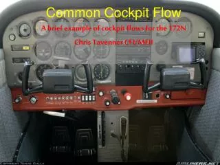
Cockpit Assembly Team. Victor Calamaro , Nick Flanagan, Rashaud Harvey, Danielle Painter. Customer Needs. Instrument the existing throttle lever with position transducers Maintain control mechanisms such as pilot interface handles, range of motion and feel

E N D
Cockpit Assembly Team Victor Calamaro, Nick Flanagan, RashaudHarvey, Danielle Painter
Customer Needs • Instrument the existing throttle lever with position transducers • Maintain control mechanisms such as pilot interface handles, range of motion and feel • Instrument the existing rudder pedals with displacement and force transducers • Maintain control mechanisms such as pilot interface pedals, range of motion and feel • Instrument the existing yoke with displacement (axial and rotational) and force transducers • Maintain control mechanisms such as pilot interface grips, range of motion and feel • Enable feedback from all transducers (force, spring rate and drag)
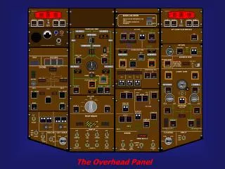
Customer Needs (cont.) • Install LCD monitor in front of each pilot station (2) • Implement an emergency stop function in multiple locations that will allow a given simulation to reset if one operation fails • Two wire (signal and return) cable • Two emergency stop switches located at each pilot station • Two switches made available for ground personnel • Clear labeling of switch function • Pull to operate, push to stop Install cabling from all transducers and monitors to the ground Interface connector for easy disconnect/replacement Rout cabling to ventilation tube and wire way conduit Provide a minimum of 10ft cabling beyond conduit exit Install mounting system for side stick inceptor. Design elbow and wrist assembly for pilot comfort
Engineering Specifications • Rudder sensor must output a position signal from 0 to 5 V • Throttle sensor must output a position signal from 0 to 5 V • Yoke sensors must output a position and rotation signal from 0 to 5 V • All controls provide X lbf feedback • Monitors are mounted in cockpit (yes/no measurement) • Emergency stop resets simulation (yes/no measurement) • All cabling is able to reach computer system (yes/no measurement) • Items in italics need to be determined
Overview • Yoke Drawback • Yoke Rotation • Throttle • LCD Display • Rudder Pedals
Pugh Matrix Weighting • Ease of Maintenance • How easy is it to get to the sensor if there is problems? • Importance - Medium • Accuracy • How close does the sensor measure position? • Importance - High • Ease of Installation • How easy is it to mount the sensor? • Importance - High • Durability • How often will the sensor need to be replaced? • Importance - Medium • Cost • How much does the sensor and associated signal conditioning cost? • Importance - Low
Yoke Drawback – Sensor Type • LVDT • Type dependent on mounting location • Most reliable, most expensive • Encoder • Similar in cost, still reliable • Quadrature Output • String Potentiometer • Type dependent on mounting location • Cheap, will wear out
Yoke Drawback – Mounting Location • Connected to yoke shaft itself • Most direct -> could be most accurate • Complex geometry causes problems • Attached to cable • Simplest • Least direct -> chance for cables to slip etc -> chance for lower accuracy
Yoke Drawback – Signal Conditioning • LVDT • Requires an expensive signal conditioning board to output 0 to 5V • Board produced by Moog • Analog board can be made • Encoder • Requires a less expensive signal conditioning board to output 0 to 5V • String Potentiometer • No conditioning necessary
Yoke Rotation – Sensor Type • RVDT/LVDT • Type dependent on mounting location • Most reliable, most expensive • Encoder • Less expensive, still reliable • Quadrature Output • Rotational/String Potentiometer • Type dependent on mounting location • Cheap, will wear out
Yoke Rotation – Mounting Location • On yoke itself • Most direct -> could be most accurate • Complex geometry causes problems • On Pulley for cables • Less direct -> slightly less accurate then on the yoke • Easier to mount then on yoke • Attached to cable • Simplest • Least direct -> chance for cables to slip etc -> chance for lower accuracy
Yoke Rotation – Signal Conditioning • RVDT/LVDT • Requires an expensive signal conditioning board to output 0 to 5V • Board produced by Moog • Analog board can be made • Encoder • Requires a less expensive signal conditioning board to output 0 to 5V • Rotational/String Potentiometer • No conditioning necessary
Throttle- Sensor Technology • Encoder • Easy installation • Durable • LVDT • Requires Signaling Board • Accurate • RVDT • Accurate • Easy installation
Throttle-Mounting Location • Between Throttle Levers • Durable • Accurate • Easily accessible
Throttle-Signaling Condition • RVDT/LVDT • Requires an expensive signal conditioning board to output 0 to 5V • Board produced by Moog • Analog board can be made • Encoder • Requires a less expensive signal conditioning board to output 0 to 5V
Rudder Pedal-Sensor • String/Rotational Potentiometer • Inexpensive • Wears out • Encoder • Durable • Reliable • LVDT/RVDT • Requires Signaling Board • Expensive • Accurate
Rudder Pedal-Mounting Location • Attached to pedal • Direct • Accessible • Cable Connection • Indirect • Slip possible
Rudder Pedal-Signaling Condition • RVDT/LVDT • Requires an expensive signal conditioning board to output 0 to 5V • Board produced by Moog • Analog board can be made • Encoder • Requires a less expensive signal conditioning board to output 0 to 5V • String/Rotational Potentiometer • No conditioning necessary
LCD Display-Technology • Flat Panel • Durable • Easy Maintenance • Compact • Monitor • Bulky • Easy Installation
LCD Display-Mounting • Bolt on Dash • Easily accessible • Durable • Velcro on Dash • Easily accessible • Cheap • Glue on Dash • Easily accessible • Easy installation